
Use and Care Manual


-12-
SANDING ACCESSORIES ASSEMBLY
B
ACKING PAD
Before attaching a backing
pad be sure its maximum safe
operating speed is not exceeded by the
nameplate speed of the tool.
Wheel guard may not be used
for most sanding operations.
Always reinstall wheel guard when converting
back to grinding operations.
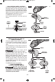
TO INSTALL BACKING PAD AND
SANDING DISC
Disconnect battery pack from tool.
Attach hand guard (Fig. 1). Set the tool on its
top side (spindle up). Place the rubber
backing pad onto the spindle shaft. Center
the sanding disc on top of the backing pad.
Insert the lock nut through the disc and
thread onto the spindle as far as you can
with your fingers. Press in the spindle lock,
then tighten the backing pad securely with
lock nut wrench (Fig. 5).
TO REMOVE: Reverse procedure.
!
WARNING
!
WARNING
SANDING
DISC
BACKING
PAD
LOCK NUT
WIRE
BRUSH
SPINDLE
FIG. 5
WIRE BRUSH ASSEMBLY
Before assembling wire brush to this tool,
disconnect from the power source. Attach
hand guard (Fig. 1). Wire brushes are
equipped with their own threaded hub, simply
thread on to spindle. Be sure to seat against
shoulder before turning tool “ON”.
TO REMOVE: Reverse procedure.
WIRE WHEEL ASSEMBLY
Before assembling wire wheel to this tool,
disconnect from the power source. Attach type
27 guard (Fig. 2). Wire wheeels are equipped
with their own threaded hub, simply thread on
to spindle. Be sure to seat against shoulder
before turning tool “ON”.
TO REMOVE: Reverse procedure.
2610041372 09-15 GWS18V-45.qxp_GWS 9/18/15 10:00 AM Page 12