
Installation Guide


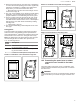

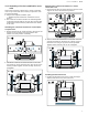
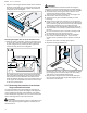
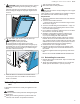
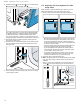
Table Of Contents
- Built-in Single, Double and Combination Ovens
- en-us
- Table of contents
- 1 IMPORTANT SAFETY INSTRUCTIONS
- 2 Before you begin
- 3 Package removal
- 4 Installation requirements
- 5 30" Single oven dimensions
- 6 30" Double oven dimensions
- 7 30" Combination oven dimensions
- 8 27" Single oven dimensions
- 9 27" Double oven dimensions
- 10 Prior to installation
- 11 Installing the ovens into the cabinet
- 12 Electrical connection
- 13 Testing the operation
- 14 Customer Service
- fr-ca
- Table des matières
- 1 IMPORTANTES CONSIGNES DE SÉCURITÉ
- 2 Avant de commencer
- 3 Élimination de l'emballage
- 4 Exigences d'installation
- 5 Dimensions pour les fours simples de 30 po
- 6 Dimensions du four double de 30 po
- 7 Dimensions du four combiné de 30 po
- 8 Dimensions du four simple de 27 po
- 9 Dimensions du four double de 27 po
- 10 Avant l'installation
- 11 Installation des fours dans l'armoire
- 12 Raccordement électrique
- 13 Opération d’essai
- 14 Service à la clientèle
- es-mx
- Tabla de contenidos
- 1 INSTRUCCIONES DE SEGURIDAD IMPORTANTES
- 2 Antes de empezar
- 3 Eliminación del embalaje
- 4 Requisitos de instalación
- 5 Medidas para hornos individuales de 30"
- 6 Medidas para el horno doble de 30"
- 7 Medidas para hornos de combinación de 30"
- 8 Medidas para hornos individuales de 27"
- 9 Medidas para el horno doble de 27"
- 10 Antes de la instalación
- 10.1 Elevación del aparato
- 10.2 Conexión del tubo del horno rápido o del horno de aire caliente y vapor al horno inferior
- 10.3 Conexión del microondas al horno inferior
- 10.4 Ensamblaje de las dos unidades del horno de combinación
- 10.5 Extracción de la puerta del horno (en modelos convencionales con bisagra inferior)
- 11 Instalación de los hornos en el gabinete
- 12 Conexión eléctrica
- 13 Comprobación del funcionamiento
- 14 Servicio de atención al cliente

en-us Prior to installation
16
1. Remove the oven-mounted junction box cover located
on the top rear of the oven.
2. Remove the cap from the conduit access hole in the
side of the oven-mounted junction box.
3. Guide the wires from the conduit cable coming from the
speed oven or steam convection oven through the hole
in the oven-mounted junction box.
4. Snap the conduit connector into the hole by pressing it
in until it clicks into place.
5. Follow the wiring diagram label; tighten securely, but do
not overtighten.
‒ Match and connect each wire by color to the wires at-
tached to the wiring block inside the oven-mounted
junction box.
‒ Push the bare end of the wire until it is snug in the
wiring block then tighten down the retaining screw on
each wire.
‒ There are four wires coming from the speed oven.
6. Replace the oven-mounted junction box cover and
tighten the two screws holding it in place. Tighten se-
curely, but do not overtighten.
10.3 Connecting the microwave to the lower
oven
The power plug of the upper microwave oven of a combi-
nation oven must be plugged into the socket on the lower
oven.
1. For microwave combination models HBL57M52UC and
HBL87M53UC and speed oven combination model
HBL8753UC: Plug the 120V plug from the microwave
into the receptacle on the top rear of the lower oven.
2. For independent microwave model HMB50152UC or
speed oven model HMC80152UC: Connect the 120V
plug from the microwave into a dedicated 120 V mi-
crowave/speed oven circuit. Refer to the installation
manual of the appliance.