
Installation Sheet
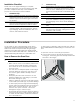
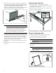
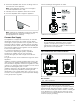
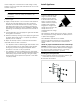
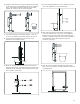
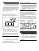
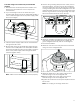
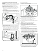
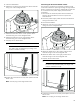
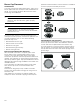
Table Of Contents
- Free-standing range
- ö Installation Instructions
- 9 Safety DefinitionsSafety Definitions
- IMPORTANT SAFETY INSTRUCTIONS
- Appliance Handling Safety
- Wear gloves to avoid cutting fingers on sharp edges during Installation.
- Unit is heavy and requires at least two persons or proper equipment to move.
- Do not lift appliance by the oven door handle. Remove the oven door for easier handling and installation See the section "Removing/Replacing the Oven Door".
- Do not use the oven for storage.
- Safety Codes and Standards
- This appliance complies with one or more of the following standards:
- It is the responsibility of the owner and the installer to determine whether additional requirements and/or standards apply to specific installations.
- Installation must conform with local codes or, in the absence of local codes, with the National Fuel Gas Code, ANSI Z223.1/NFPA 54 or, in Canada, the Natural Gas and Propane Installation Code, CSA B149.1.
- The appliance must be electrically grounded in accordance with local codes or, in the absence of local codes, with the National Electrical Code, NFPA 70 latest edition or, in Canada, the Canadian Electric Code, CSA C22.1-02.
- Electric Safety
- WARNING
- Be sure your appliance is properly installed and grounded by a qualified technician. Installation, electrical connections and grounding must comply with all applicable codes.
- Before installing, turn power OFF at the service panel. Lock service panel to prevent power from being turned ON accidentally.
- For appliances equipped with a cord and plug, do not cut or remove the ground prong. It must be plugged into a matching grounding type receptacle to avoid electrical shock. If there is any doubt as to whether the wall receptacle is properly grounded,...
- Do not use an extension cord.
- Do not use an adapter.
- If required by the National Electrical Code (or Canadian Electrical Code), this appliance must be installed on a separate branch circuit.
- The circuit breaker should have a contact separation of at least 3 mm on all poles.
- Installer – show the owner the location of the circuit breaker or fuse. Mark it for easy reference.
- Refer to rating label for more information. See "How to Obtain Warranty Service" under "Customer Service" for rating label location.
- Gas Safety
- Install a gas shutoff valve near the appliance. It must be easily accessible in an emergency.
- Leak testing must be conducted by the installer according to the instructions in this manual.
- The appliance and its individual shutoff valve must be disconnected from the gas supply piping system during any pressure testing at pressures in excess of ½ psi (3.5 kPa).
- The appliance must be isolated from the gas supply piping system by closing its individual manual shutoff valve during any pressure testing of the gas supply piping system at test pressures equal to or less than ½ psi (3.5 kPa).
- The minimum supply pressure must be 1" water column above the manifold pressure printed on the rating label. The maximum supply pressure must not exceed 14.0 inches water column (34.9 Millibars).
- A metal flex line or fixed metal pipe shall be used to connect gas to the appliance. If a metal gas line cannot be used, consult your local certified electrician or local electric codes for proper grounding.
- This product may contain a chemical known to the State of California, which can cause cancer or reproductive harm. Therefore, the packaging of your product may bear the following label as required by California:
- Propane Gas Installation
- The propane gas tank must be equipped with its own high pressure regulator. In addition, the regulator supplied with this unit must also be used.
- The appliance is shipped from the factory for use with natural gas. It must be converted for use with propane. A qualified technician or installer must do the conversion.
- This appliance has been certified for safe operation up to a height of 10,000 ft. Exception: To use it with propane gas, the appliance must be converted in accordance with the propane conversion instructions.
- Installer - show the owner where the gas shut-off valve is located.
- Related Equipment Safety
- The appliance should only be used if installed by a qualified technician in accordance with these installation instructions and all applicable regulations and codes. The manufacturer is not responsible for damages resulting from incorrect installation.
- Remove all tape and packaging before using the appliance. Destroy the packaging after unpacking the appliance. Never allow children to play with packaging material.
- Never modify or alter the construction of the appliance. For example, do not remove leveling legs, panels, wire covers or anti-tip brackets/screws.
- To eliminate the risk of burns or fire by reaching over heated surface units, cabinet storage space located above the surface units should be avoided. If cabinet storage is to be provided, the risk can be reduced by installing a hood that projects ho...
- Verify that cabinets above the cooktop are a maximum of 13" (330 mm) deep.
- When installing a cooktop over a single oven, be sure to follow both the oven’s and cooktop’s installation manuals.
- Ventilation Recommendations
- We strongly recommend the installation of a ventilation hood above this appliance. The hood must be installed according to instructions furnished with the hood.
- Conversion to Propane Gas
- High Altitude Installation
- Parts Included
- Removing Packaging
- General Information
- Cabinet Requirements
- X = Grounded Outlet
- Y = Gas Supply Line
- The minimum spaces that must be maintained when installing the gas cooktop shall be:
- Choose one of the following built-in configurations.
- Installation allowed only with non combustible back wall
- * Clearances from non-combustible materials are not part of the ANSI Z21.1 scope and are not certified by Intertek. Clearances of less than 3'' (76 mm) should be approved by the local codes and/or by the local authority having jurisdiction.
- Island Installation (applicable both with non combustible back wall and combustible back wall)
- * purchased separately
- ** Clearances from non-combustible materials are not part of the ANSI Z21.1 scope and are not certified by Intertek. Clearances of less than 3'' (76 mm) should be approved by the local codes and/or by the local authority having jurisdiction.
- Low Backguard Installation (applicable both with non combustible back wall and combustible back wall)
- * purchased separately
- ** Clearances from non-combustible materials are not part of the ANSI Z21.1 scope and are not certified by Intertek. Clearances of less than 3'' (76 mm) should be approved by the local codes and/or by the local authority having jurisdiction.
- Technical Data
- Installation Checklist
- How to Remove the Oven Door
- 9 WARNING
- To avoid injury or damage, make sure that you read the above WARNING before attempting to remove the oven door.
- 1. Open the oven door to its fully open position.
- 2. Lock the two hinges on the left and right using the locking pin. The locking pins must be fully inserted into the holes in the hinges.
- 3. Close the oven door until it catches on the hinge stop levers, locking the hinges at the correct angle for door removal. The door can be removed when it is pulled up from the open position by about 8 inches (203 mm). This takes the tension off the...
- 9 CAUTION
- Risk of pinching
- 4. The door is heavy. Use both hands to firmly grip it by the sides. Do not grip the door by the handle. Keeping the angle of the door the same, lift the door straight up approximately 3/4" (19 mm) to unhook the hinges from the slots, and then pull i...
- 5. Place the door in a convenient and stable location for cleaning.
- 6. Refit the door in the reverse order in which it was removed.
- Risk of pinching
- Fitting the Rear Vent Trim
- Fitting the Adjustable Feet
- Connect Gas Supply
- The appliance is shipped from the factory for use with natural gas at a pressure of 5" water column. When checking for proper operation of the regulator, the inlet pressure must be at least 1" greater than the operating (manifold) pressure above. Whe...
- To convert the appliance to propane gas see “Conversion to propane gas (LPG)”. A qualified technician or installer must do the conversion.
- Use a flexible gas pipe with a length of at least 5 ft (1.5 m).
- The gas inlet to the unit is located at the right rear of the appliance.
- Install the pressure regulator (supplied with unit) to gas inlet. Postion the gasket (supplied with unit) in between the inlet and the regulator. Position the regulator to have it cap D (~ Page 23) easily accessible. Turn the nut on gas inlet to hand...
- Install the gas pipe to the regulator using Teflon tape or pipe-joint compound (resistant to propane gas and natural gas). Turn to hand tighten plus 1/3 turn. Do not exceed 1 turn for alignment, to prevent possible damage to the gas pressure regulator.
- Check inlet fittings and regulator for leaks.
- * Attached to the appliance.
- Side and Back View Gas Cooker Installation
- Connect the gas supply line to the unit pressure regulator using a 1/2” flex gas line connector between manual shut-off valve and pressure regulator. A metal flex line or fixed metal pipe shall be used to connect gas to the appliance. If a metal ga...
- Check supply line connections for leaks using a soap solution or non-corrosive leak detection fluid. Do not use a flame of any sort.
- 1. Turn on gas.
- 2. Apply a soap solution or non-corrosive leak detection fluid to all joints and fittings in the gas connection between the shut-off valve and the cooktop. Include gas fittings and joints in the cooktop if connections may have been disturbed during i...
- 3. If a leak appears, turn off supply line gas shut-off valve and tighten connections.
- 4. Retest for leaks by turning on the supply line gas shut- off valve. When leak check is complete (no bubbles appear), test is complete.
- 5. Wipe off all soap solution or detection fluid residue.
- Important Notes for Gas Connection:
- Install Appliance
- 9 WARNING
- Installing the anti-tip bracket
- 1. Ensure that the electrical connection and the gas connection are in the correct position.
- 2. Assemble the bracket.
- 3. Align the base of the hook of the bracket with the base on the slot of the rear wall fastening bracket. Align the base of the fastening bracket with the ground and tighten the screws to fix the measurements.
- 4. For wall mounting, proceed with steps 5–7 and 10.
- 5. Use the specified distance from the side of the appliance to the bracket holes.
- 6. Move the bracket onto the wall and fix with the two washers and screws. A qualified technician must verify suitability of the materials in accordance with the type and condition of the wall.
- 7. Use the following distances for the distance from the side of the appliance to the bracket holes.
- 8. After having positioned and leveled the appliance, move the bracket close to the rear of the appliance and anchor it to the floor with the two washers and screws. A qualified technician must verify suitability of the materials in accordance with t...
- 9. Push the cooker towards the wall, and at the same time, insert the bracket in the plate fastened to the rear of the appliance.
- 10. Check for proper installation and use of the anti-tip bracket. Carefully tip the range forward pulling from the back to ensure that the anti-tip bracket engages the range leg and prevents tip-over. The range should not move more than 1” (2.5cm).
- Connect Electrical Supply
- The Dual Fuel slide in range may be connected using an electric range cord or using a flexible conduit electrical connection. The length must be at least 1,5 m.
- For technical specifications see the rating label on the underside of the projecting control panel.
- Do not use multiple outlets, extension leads or adapters.
- For installations other than those in Canada, connect the range cord at the terminal block. Access the terminal block by removing the cover in the lower right-hand corner of the range back panel.
- Preparation for Power Connection
- For installations where grounding through the neutral conductor is prohibited: (a) disconnect the link from the neutral, (b) use grounding terminal or lead to ground unit, (c) connect neutral terminal to lead branch circuit neutral in the usual manne...
- Use only cord kits rated 208/240 volts, 50 amperes, with ring or fork type connector and labelled "For use with ranges”. Use only flexible conduit with wires with ring or fork type connectors. Strain relief provided with the cord must be installed ...
- Four-wire range cord connection (recommended method)
- 1. Disconnect the electrical power at the breaker box. Remove the terminal block cover to expose the terminal block.
- 2. If you need a lager hole for the strain relief (not provided with range) remove the metal plate. Rotate it 180° to have the lager hole for the power supply cable and mount it again.
- 3. Insert the power supply cable into the terminal block through the bottom hole.
- 4. Mount strain relief (not provided with range) through the hole of the metal plate in the back panel located below the terminal block and secure tightly. Route the wires of the power supply cable through the strain relief and tighten clamp.
- Note:
- 5. Remove the grounding strap from the center post on the terminal block. Therefore remove the hexagonal nut of the neutral pin. Remove the fork type connector of the groundling link. Mount the hexagonal nut on the neutral pin again. Remove the green...
- 6. Attach the insulated grounding wire to the grounding hole with the green grounding screw. Tighten the green hexagonal nut firmly, but do not overtighten.
- 7. Insert the flat washer.
- 8. Attach the red wire to the left junction block terminal using one of the hexagonal nuts.
- 9. Attach the white wire to the center junction block terminal using one of the hexagonal nuts.
- 10. Attach the black wire to the right junction block terminal using one of the hexagonal nuts.
- 11. Tighten all connections securely and replace terminal block cover.
- Note:
- Connecting the three-wire range cord (alternate method)
- The four-wire connection (above) is preferred, but where local codes and ordinances permit grounding through the neutral and where conversion to four-wire is impractical, the unit can be connected to the power supply via a three-wire connection.
- 1. Disconnect the electrical power at the breaker box. Remove the terminal block cover to expose the terminal block.
- 2. If you need a lager hole for the strain relief (not provided with range) remove the metal plate. Rotate it 180° to have the lager hole for the power supply cable and mount it again.
- 3. Insert the power supply cable into the terminal block through the bottom hole.
- 4. Mount strain relief (not provided with range) through the hole of the metal plate in the back panel located below the terminal block and secure tightly. Route the wires of the power supply cable through the strain relief and tighten clamp.
- Note:
- 5. Insert the flat washer.
- 6. Attach the red wire to the left junction block terminal using one of the hexagonal nuts.
- 7. Attach the white wire to the center junction block terminal using one of the hexagonal nuts.
- 8. Attach the black wire to the right junction block terminal using one of the hexagonal nuts.
- 9. Tighten all connections securely and replace terminal block cover.
- Note:
- Connecting the four-wire flexible conduit
- 1. Disconnect the electrical power at the breaker box. Remove the terminal block cover to expose the terminal block.
- 2. Insert the power supply cable into the terminal block through the bottom hole.
- 3. Remove the grounding strap from the center post on the terminal block. Therefore remove the hexagonal nut of the neutral pin. Remove the fork type connector of the groundling link. Mount the hexagonal nut on the neutral pin again. Remove the green...
- 4. Attach the insulated grounding wire to the grounding hole with the green grounding screw. Tighten the green hexagonal nut firmly, but do not overtighten.
- 5. Insert the flat washer.
- 6. Attach the red wire to the left junction block terminal using one of the hexagonal nuts.
- 7. Attach the white wire to the center junction block terminal using one of the hexagonal nuts.
- 8. Attach the black wire to the right junction block terminal using one of the hexagonal nuts.
- 9. Properly secure strain relief.
- Warning
- Note:
- Connecting the three-wire flexible conduit
- The four-wire connection is preferred, but where local codes and ordinances permit grounding through neutral and/or conversion to four-wire is impractical, the unit can be connected to the power supply via a three-wire connection.
- 1. Disconnect the electrical power at the breaker box. Remove the terminal block cover to expose the terminal block.
- 2. Insert the power supply cable into the terminal block through the bottom hole.
- 3. Insert the flat washer.
- 4. Attach the red wire to the left junction block terminal using one of the hexagonal nuts.
- 5. Attach the white wire to the center junction block terminal using one of the hexagonal nuts.
- 6. Attach the black wire to the right junction block terminal using one of the hexagonal nuts.
- 7. Properly secure strain relief.
- Warning
- Note:
- Burner Cap Placement
- Sealed burners
- Your new cooktop has sealed gas burners. There are no burner parts under the cooktop to clean, disassemble or adjust. Your cooktop has three different burner sizes: small, large and dual-flame.
- The burner parts must be correctly positioned for the cooktop to function properly. If the burner parts are not correctly positioned, one or more of the following problems may occur:
- Burner Cap and Burner Base Placement After electrical connection is complete, place each burner base on the corresponding location on the cooktop. One of the three bars on the burner base should line up with the notch and prevent the base from rotati...
- Once each base is located and resting evenly, place each burner cap on its correct burner base. See Illustration.
- Place burner cap gently on top of base so that the prongs of the burner base fit snugly into the groove of the burner cap.
- If the maintop is removed by a certified installer (for example to check electrical or piping connection) the panhead screws that were removed must be re-installed to ensure proper functionality of burners.
- Checking Burner Cap Placement Check to make sure that there is no gap between the burner cap and burner base. See illustration below for correct and incorrect placements of the burner cap.
- You may gently try to move the burner cap from side to side to check if it is properly placed. If properly placed, the cap will click from side to side as the prongs hit the groove ridge.
- Install Grates First position the outer grates, followed by the the central grate. If you only have two grates, the order in which you position them is not relevant.
- Check the Installation
- Place each correct-sized burner cap in its seated, notched position and check the operation of the electric igniters. Check the flame characteristics. The flame should be blue with a minimal yellow tip on the outer cone of the flames.
- Some yellow streaking is normal during the initial start- up. Allow the appliance to operate for 4–5 minutes and reevaluate before making adjustments.
- Test for Gas Leaks
- 9 WARNING
- Leak testing is to be conducted by the installer according to the instructions given in this section.
- 1. Turn on gas.
- 2. Apply a non-corrosive leak detection fluid. Include all joints and fittings between the shutoff valve and the appliance. Include gas fittings and joints in the appliance if connections may have been disturbed during installation.
- 3. Inspect for leaks. Bubbles appearing around fittings and connections indicate a leak.
- 4. If a leak appears, turn off supply line gas shutoff valve and tighten connections.
- 5. Retest for leaks. Turn gas back on at supply line shutoff valve and reapply leak detection fluid.
- 6. When no bubbles appear, test is complete. Wipe off all detection fluid residue.
- Conversion to Propane Gas (LPG)
- Always provide adequate gas supply.
- This appliance is shipped from the factory for use with natural gas. Use this kit to convert the appliance for propane gas use if necessary. Observe the following:
- Ensure that the range is converted for use with the appropriate gas before using it.
- This appliance is designed to operate at a pressure of 10" water column when used with propane gas.
- When checking for proper operation of the regulator, the inlet pressure must be at least 1" greater than the operating (manifold) pressure above. When converting for propane gas use, the pressure supplied to the regulator must be between 11" and 13" ...
- The pressure regulator that is located in the inlet of the range manifold must remain in the supply line.
- Use a flexible metal appliance connector or rigid pipe to connect the range to the gas supply. The connector should have an inner diameter of 1/2” and be 5 ft (1.5 m) or less in length. (Exception: Maximum connector length in Massachusetts installa...
- Save the orifices removed from the appliance for future use.
- Parts included with propane gas nozzle set:
- 30”
- 36”
- Orifices
- Setting the pressure regulator for propane gas
- 1. Use tongue and groove pliers to remove regulator cap D.
- 2. Unscrew the plastic regulator stem from the regulator cap D.
- 3. Invert the plastic regulator stem and screw it in tightly.
- 4. Replace cover cap D and tighten with tongue & groove pliers.
- 5. When converting for propane gas use, the pressure supplied to the regulator must be between 11" and 13" water column.
- Replacing the main control nozzles
- 1. Remove the grates.
- 1. Remove the control knob and knob ring.
- 2. Turn the inner setting screw clockwise gently until it bottoms out.
- Note:
- 3. Replace the control knobs.
- 4. Light each burner individually and check for flame stability on low setting.
- 5. If required, loosen the setting screw to increase the gas flow.
- 6. Ensure that the flame does not go out when the gas flow is quickly changed between maximum and minimum, and vice versa. The optimum setting is achieved when the height of the small flame is approx. 1/8" (3 to 4 mm).
- 7. Refit the control knob and knob ring for the gas burner.
- 8. Repeat steps 2 to 8 until all of the gas burners have been set.
- 9. Connect the appliance to the power supply.
- Checking functions after the conversion: The flames must not go out when switching over swiftly from the high to the low setting.
- Test for Gas Leaks
- After the conversion it is important to verify the leakages. ~ Page 21
- Conversion to natural gas
- This appliance is shipped from the factory for use with natural gas. If the appliance has been converted to propane gas before, you have to convert it to natural gas again.
- Check the orifices for the right nozzles and, if required, replace them. See "Replacing the main control nozzles".
- Adjust the minimum gas flow. See "Setting the minimum gas flow". The optimum setting is achieved when the height of the small flame is approx. 1/8" (3 to 4 mm).
- Set the pressure regulator for natural gas. Turn the spring plate the other way around as shown in "Setting the pressure regulator for propane gas".
- Save the orifices removed from the appliance for future use.
- Contact our Customer Service if your appliance needs repair. Our Customer Service (see below) will be happy to supply you with details how to obtain a service repair.
- Please find the contact data of all countries in the enclosed customer service list.
- How to Obtain Warranty Service
- Õ Instructions d’installation
- 9 Définitions de sécuritéDéfinitions de sécurité
- CONSIGNES DE SÉCURITÉ IMPORTANTES
- LIRE ET CONSERVER CES INSTRUCTIONS
- important : il faut faire poser l'appareil par un installateur qualifié.
- INSTALLATEUR : LAISSEZ CES INSTRUCTIONS AVEC L'APPAREIL APRÈS UNE FOIS L'INSTALLATION TERMINÉE. IMPORTANT : À CONSERVER POUR L'USAGE DE L'INSPECTEUR LOCAL.
- La garantie ne couvre pas une mauvaise installation.
- Sécurité de manutention des appareils
- Portez des gants pour éviter de vous couper les doigts sur les bords tranchants pendant l'installation.
- Le bloc est lourd et nécessite au moins deux personnes ou bien un équipement approprié pour le déplacement.
- Ne soulevez pas l'appareil par la poignée de la porte du four. Retirez la porte du four pour faciliter la manipulation et l'installation. Voir la section "Démontage/ remplacement de la porte du four".
- N'utilisez pas le four pour le stockage.
- Codes et normes de sécurité
- Cet appareil est conforme à une ou plusieurs des normes suivantes :
- Il incombe au propriétaire et à l'installateur de déterminer si des exigences et/ou des normes supplémentaires s'appliquent à des installations spécifiques.
- L’installation doit être conforme aux codes locaux ou, en l’absence de tels codes, au National Fuel Gas Code ANSI Z223.1/NFPA 54 ou, au Canada, au code national CSA B149.1 d’installation du gaz naturel et du propane.
- L’appareil doit être mise à la terre en conformité aux codes locaux, ou en l’absence de tels codes, à la dernière version du National Electric Code NFPA 70 ou, au Canada, au code canadien de l’électricité CSA C22.1-02.
- Sécurité électrique
- AVERTISSEMENT
- S'assurer que l'appareil est installé et mis à la terre par un technicien qualifié. L'installation, les connexions électriques et la mise à la terre doivent être conformes à tous les codes applicables.
- Avant l'installation, mettre l'appareil hors service au panneau de service. Verrouiller le panneau d'entrée d'électricité pour éviter que le courant ne soit accidentellement rétabli.
- Pour les appareils dotés d'un cordon et d'une fiche, ne pas couper ou enlever la broche de mise à la terre. Le cordon doit être branché dans une prise de courant adaptée de type mise à la terre pour éviter tout risque d'électrocution. S'il y ...
- N'utilisez pas de rallonge.
- N'utilisez pas d’adaptateur.
- S'il y a lieu, conformément au Code national de l'électricité (ou au Code canadien de l'électricité), cet appareil doit être installé sur un circuit de dérivation séparé.
- Le disjoncteur doit avoir une séparation de contact de 3 mm. minimum pour tous les pôles.
- Installateur – Indiquer au propriétaire l’emplacement du disjoncteur ou du fusible. Identifier sa position pour pouvoir le retrouver facilement.
- Consultez la plaque signalétique pour de plus amples renseignements. Voir « Comment obtenir une garantie » dans le « Service à la clientèle » pour connaître l'emplacement de l'étiquette signalétique.
- Sécurité en matière de gaz
- Installer un robinet d'arrêt de gaz à proximité de l'appareil. Celui-ci doit être facilement accessible en cas d'urgence.
- Les essais d'étanchéité doivent être effectués par l'installateur conformément aux instructions du présent manuel.
- L'appareil et le robinet individuel de fermeture à commande manuelle dont il est muni doivent être déconnectés du système de canalisations de gaz lors de tout contrôle de pression où la pression d'essai est supérieure à ½ psi (3,5 kPa).
- L'appareil doit être isolé du système de canalisations de gaz en fermant le robinet individuel de fermeture à commande manuelle dont il est muni pendant tout contrôle de pression du système de canalisations de gaz à des pressions d'essai infé...
- La pression minimale d'alimentation doit être de 1 po CE au-dessus de la pression du distributeur, tel qu'indiqué sur la plaque signalétique. La pression maximale d'alimentation ne pas dépasser 14 po CE (34,9 millibars).
- Une ligne de production métallique souple ou un tuyau métallique fixe doit être utilisé pour raccorder le gaz à l'appareil. Si une conduite de gaz en métal ne peut pas être utilisée, veuillez vous adresser à un électricien agréé local ou ...
- Ce produit pourrait contenir un produit chimique reconnu par l'État de la Californie comme cancérigène ou ayant des effets nocifs sur la reproduction. Par conséquent, l'emballage de votre produit pourrait porter l'étiquette suivante, comme requi...
- Installation au gaz propane
- La bouteille de gaz propane doit comporter son propre régulateur haute pression. De plus, le régulateur fourni avec cet appareil doit également être utilisé.
- L'appareil est expédié depuis l'usine pour être utilisé avec du gaz naturel. S'il doit être utilisé avec du gaz propane, il doit être converti. Un technicien ou installateur qualifié devra se charger de la conversion.
- Cet appareil a été certifié pour un fonctionnement sécuritaire à une hauteur maximale de 10 000 pi. Exception : pour l'utiliser avec du gaz propane, l'appareil doit être converti conformément aux instructions de conversion au propane.
- Installateur - montrez au propriétaire où se trouve le robinet d'arrêt de gaz.
- Équipement de sécurité
- l' appareil ne doit être utilisé que s'il est installé par un technicien qualifié conformément à ces instructions d'installation et à tous les règlements et codes. Le fabricant n'est pas responsable des dommages résultant d'une installation ...
- Enlever le ruban adhésif et l’emballage avant d’utiliser l’appareil. Détruire l’emballage après avoir déballé l’appareil. Ne jamais laisser les enfants jouer avec les matériaux de conditionnement.
- Ne jamais modifier ni altérer la configuration de l'appareil. Par exemple, ne pas retirer les pieds de nivellement, les panneaux, les couvercles de câblage ou les fixations/vis antibasculement.
- Pour éliminer le risque de brûlures ou d’incendie lorsque l’on allonge le bras au-dessus des éléments de surface chauds, éviter d’installer des placards au-dessus des éléments de surface. Si l’installation de placards est prévue, le r...
- Vérifiez que la profondeur des armoires situées au- dessus de la table de cuisson ne dépasse pas 13 po (330 mm).
- Lors de l'installation de la table de cuisson sur un four simple, prendre bien soin de suivre les instructions des manuels d'installation du four et de la table de cuisson.
- Recommandations sur la ventilation
- Il est vivement recommandé d'installer une hotte aspirante au-dessus de cet appareil. La hotte aspirante doit être installée conformément aux instructions qui l'accompagnent.
- Conversion gaz au propane
- Installation à altitude élevée
- Pièces comprises
- Pour enlever l’emballage
- Informations générales
- Exigences pour les placards
- X = Prise de mise à la terre
- Y = Conduite d'alimentation en gaz
- Les espaces minimaux qui doivent être respectés lors de l'installation de la plaque de cuisson au gaz doivent être les suivants :
- Choisir l'une des configurations intégrées suivantes.
- Installation autorisé uniquement avec paroi arrière non combustible
- * Dégagements par rapport aux matériaux non combustibles ne font pas partie du domaine d'application ANSI Z21.1 et ne sont pas certifiés par Intertek. Les dégagements de moins de 3 po (76 mm) doivent être approuvés par le et / ou par l'autorit...
- Installation de l'îlot (applicable à la fois avec paroi arrière non combustible et mur arrière combustible)
- * Acheté séparément
- ** Dégagements des matériaux incombustibles ne font pas partie du domaine d'application ANSI Z21.1 et ne sont pas certifiés par Intertek. Les dégagements de moins de 3 po (76 mm) doivent être approuvés par le et / ou par l'autorité locale com...
- Protection arrière basse Installation (applicable à la fois avec paroi arrière non combustible et paroi arrière combustible)
- * Acheté séparément
- ** Dégagements des matériaux incombustibles ne font pas partie du domaine d'application ANSI Z21.1 et ne sont pas certifiés par Intertek. Les dégagements de moins de 3 po (76 mm) doivent être approuvés par le et / ou par l'autorité locale com...
- Caractéristiques techniques
- Liste de contrôle pour l'installation
- Démontage de la porte du four
- 9 AVERTISSEMENT
- Pour éviter de vous blesser ou d'endommager l'appareil, lisez attentivement l'AVERTISSEMENT ci-dessus avant d'essayer d'enlever la porte du four.
- 1. Ouvrez complètement la porte du four.
- 2. Verrouillez les charnières gauche et droite à l'aide de la goupille de verrouillage. Les goupilles de verrouillage doivent être complètement insérées dans les trous des charnières.
- 3. Fermez la porte du four jusqu'à ce qu'elle s'enclenche sur les leviers d'arrêt des charnières tout en verrouillant ces dernières selon l'angle correct pour le retrait de la porte. La porte peut être retirée lorsqu'elle est soulevée d'enviro...
- 9 ATTENTION
- Risque de pincement
- 4. La porte est lourde. Saisissez les côtés de la porte fermement et des deux mains. Ne saisissez pas la porte par la poignée. En maintenant l'angle de la porte au même niveau, soulevez cette dernière d'environ 3/ 4 po (19 mm) vers le haut pou...
- 5. Placez la porte dans un endroit pratique et stable pour le nettoyage.
- 6. Replacez la porte dans l'ordre inverse dans lequel elle a été retirée.
- Risque de pincement
- Ajustement de la garniture de ventilation arrière
- Montage des pieds réglables
- Branchement du gaz
- L'appareil électroménager est livré de l'usine prêt à utiliser avec du gaz naturel à une pression de 5 po de la colonne d'eau. Lors de la vérification du bon fonctionnement du régulateur, la pression d'entrée doit être supérieure d'au moi...
- Pour convertir l'appareil au gaz propane, voir « Conversion au gaz propane (GPL) ». Un technicien ou un installateur qualifié doit procéder à la conversion.
- Utilisez un tuyau de gaz flexible d'une longueur d'au moins 5 pi (1,5 m).
- L'admission de gaz de l'appareil est située à droite, à l'arrière de l'appareil.
- Installez le régulateur de pression (fourni avec l'appareil) à l'entrée du gaz. Positionner le joint (fourni avec l'unité) entre l'entrée et le régulateur. Positionnez le régulateur pour avoir le capuchon D (~ Page 47) facilement accessible. T...
- Installez le tuyau de gaz au régulateur à l'aide d'un ruban de Téflon ou de pâte à joint (résistant au gaz au propane et au gaz naturel). Serrez à la main puis tournez 1/3 de tour. Ne tournez pas plus de 1 tour lors de l'alignement, pour év...
- Vérifiez les raccords d'entrée ainsi que le régulateur pour détecter la présence de fuites.
- * Fixé à l'appareil.
- Vue latérale et arrière de l'installation de la cuisinière à gaz
- Raccordez la conduite d’alimentation en gaz au régulateur de pression de l’appareil avec un connecteur souple de gaz de 1/2 po entre le robinet d’arrêt manuel et le régulateur de pression. Une ligne de production métallique souple ou un tuy...
- Vérifiez les raccords de la conduite d'alimentation pour détecter les fuites en utilisant une solution savonneuse ou un liquide de détection de fuites non corrosif. N'utilisez jamais de flamme de quelque nature que ce soit.
- 1. Ouvrez le gaz.
- 2. Appliquez une solution savonneuse ou un liquide de détection de fuites non corrosif à toutes les jonctions et tous les raccords des conduites de gaz entre le robinet d’arrêt et la table de cuisson. Incluez les raccords et les jonctions de gaz...
- 3. En présence d’une fuite, coupez l’alimentation en gaz en fermant le robinet d’arrêt et serrez le ou les raccords qui fuient.
- 4. Testez de nouveau la présence de fuites en ouvrant le robinet d’arrêt de l’alimentation de gaz. Lors de la vérification des fuites est terminé (aucune bulle n'apparaît), le test est terminé.
- 5. Essuyez tout résidu de la solution savonneuse ou du liquide de détection de fuite.
- Remarques importantes concernant le raccord au gaz :
- Pose de l'appareil
- 9 AVERTISSEMENT
- Montage de la console anti-basculement
- 1. Veillez à ce que le raccordement électrique et le raccordement du gaz soient en position correcte.
- 2. Assemblez les supports.
- 3. Orientez la base du crochet du support avec la base de la fente du support de fixation murale arrière. Alignez la base du support de fixation avec le sol et serrez les vis pour fixer les mesures.
- 4. Pour le montage mural, procéder aux étapes 5-7 et 10.
- 5. Respectez la distance spécifiée entre le côté de l'appareil et les trous des supports.
- 6. Déplacez le support sur le mur et fixer avec les deux rondelles et vis. Un technicien qualifié doit vérifier l'adéquation des matériaux en fonction du type et de l'état du mur.
- 7. Respectez les distances suivantes pour déterminer la distance entre le côté de l'appareil et les trous des supports.
- 8. Après avoir positionné et mis à niveau l'appareil, rapprochez le support à l'arrière de l'appareil et fixez-le au sol avec les deux rondelles et vis. Un technicien qualifié doit vérifier l'adéquation des matériaux en fonction du type et d...
- 9. Déplacez la cuisinière vers le mur et, en même temps, insérez le support dans la plaque fixée à l'arrière de l'appareil.
- 10. Vérifiez que le support anti-basculement est correctement installé et utilisé. Basculez avec précaution la cuisinière vers l'avant en tirant de l'arrière pour vous assurer que le support anti- basculement engage le pied de la cuisinière et...
- Brancher l'alimentation électrique
- La cuisinière à glissière bi-carburation peut être raccordée à l'aide d'un cordon de cuisinière électrique ou d'un raccord électrique à conduit flexible. La longueur doit être d'au moins 1,5 m.
- Pour les spécifications techniques, voir l'étiquette signalétique sur le dessous du panneau de commande de projection.
- N'utilisez pas de rallonge, de bloc multiprise ou d'adaptateur.
- Pour les installations autres que celles du Canada, raccordez le cordon de la cuisinière au bornier. Accédez au bornier en retirant le couvercle situé dans le coin inférieur droit du panneau arrière de la cuisinière.
- Préparation du raccordement électrique
- Les installations pour lesquelles la mise à la terre via le conducteur neutre est interdite : (a) déconnectez la liaison du neutre, (b) utilisez la borne de mise à la terre ou le conducteur de dérivation du neutre, (c) connectez la borne du neutr...
- N'utilisez que des trousses de câbles électriques de 208/240 volts, 50 ampères, avec cosse à oeillet ou à fourche et portant l'étiquette « Pour utilisation avec les cuisinières ». Utiliser un conduit flexible avec cables avec cosse à oeil...
- Liaison par cordon à quatre fils de la cuisinière (méthode recommandée)
- 1. Débranchez l'alimentation électrique au niveau du boîtier des disjoncteurs. Retirez le couvercle du bornier pour mettre le bornier à découvert.
- 2. Si vous avez besoin d'un trou plus grand pour la décharge de traction (non fourni avec la cuisinière), retirez la plaque métallique. Faites-le pivoter de 180 ° pour avoir un plus grand trou pour le câble d'alimentation et montez-le à nouveau.
- 3. Insérez le câble d'alimentation électrique dans le bornier en le faisant passer par le trou inférieur.
- 4. Montez le réducteur de tension (non fourni avec la cuisinière) à travers le trou de la plaque métallique dans le panneau arrière situé sous le bornier et fixez fermement. Acheminez les fils du câble d'alimentation à travers la décharge de...
- Remarque :
- 5. Retirez la barrette de mise à la terre du poteau central du bornier. Retirez ainsi l'écrou hexagonal de la broche neutre. Retirez le connecteur de type fourche de la liaison de mise à la terre. Remontez l'écrou hexagonal sur la broche neutre. ...
- 6. Fixez le fil de terre isolé au trou de terre à l'aide de la vis de mise à la terre verte. Vissez fermement l'écrou hexagonal vert, mais ne serrez pas trop fort.
- 7. Insérez la rondelle plate.
- 8. Fixez le fil rouge à la borne gauche du bloc de raccordement à l'aide d'un des écrous hexagonaux.
- 9. Fixez le fil blanc à la borne centrale du bloc de raccordement à l'aide d'un des écrous hexagonaux.
- 10. Raccordez le fil noir à la borne droite du bloc de raccordement à l'aide d'un des écrous hexagonaux.
- 11. Vissez bien tous les raccordements et replacez le couvercle du bornier.
- Remarque :
- Raccordement du cordon à trois fils de la cuisinière (autre méthode)
- La liaison à quatre fils (ci-dessus) est préférable, mais lorsque les codes et arrêtés municipaux permettent la mise à la terre par le neutre et lorsque la conversion en liaison à quatre fils n'est pas pratique, l'appareil peut être raccordé...
- 1. Débranchez l'alimentation électrique au niveau du boîtier des disjoncteurs. Retirez le couvercle du bornier pour mettre le bornier à découvert.
- 2. Si vous avez besoin d'un trou plus grand pour la décharge de traction (non fourni avec la cuisinière), retirez la plaque métallique. Faites-le pivoter de 180 ° pour avoir un plus grand trou pour le câble d'alimentation et montez-le à nouveau.
- 3. Insérez le câble d'alimentation électrique dans le bornier en le faisant passer par le trou inférieur.
- 4. Montez le réducteur de tension (non fourni avec la cuisinière) à travers le trou de la plaque métallique dans le panneau arrière situé sous le bornier et fixez fermement. Acheminez les fils du câble d'alimentation à travers la décharge de...
- Remarque :
- 5. Insérez la rondelle plate.
- 6. Fixez le fil rouge à la borne gauche du bloc de raccordement à l'aide d'un des écrous hexagonaux.
- 7. Fixez le fil blanc à la borne centrale du bloc de raccordement à l'aide d'un des écrous hexagonaux.
- 8. Raccordez le fil noir à la borne droite du bloc de raccordement à l'aide d'un des écrous hexagonaux.
- 9. Vissez bien tous les raccordements et replacez le couvercle du bornier.
- Remarque :
- Raccordement du conduit électrique flexible à quatre fils
- 1. Débranchez l'alimentation électrique au niveau du boîtier des disjoncteurs. Retirez le couvercle du bornier pour mettre le bornier à découvert.
- 2. Insérez le câble d'alimentation électrique dans le bornier en le faisant passer par le trou inférieur.
- 3. Retirez la barrette de mise à la terre du poteau central du bornier. Retirez ainsi l'écrou hexagonal de la broche neutre. Retirez le connecteur de type fourche de la liaison de mise à la terre. Remontez l'écrou hexagonal sur la broche neutre. ...
- 4. Fixez le fil de terre isolé au trou de terre à l'aide de la vis de mise à la terre verte. Vissez fermement l'écrou hexagonal vert, mais ne serrez pas trop fort.
- 5. Insérez la rondelle plate.
- 6. Fixez le fil rouge à la borne gauche du bloc de raccordement à l'aide d'un des écrous hexagonaux.
- 7. Fixez le fil blanc à la borne centrale du bloc de raccordement à l'aide d'un des écrous hexagonaux.
- 8. Raccordez le fil noir à la borne droite du bloc de raccordement à l'aide d'un des écrous hexagonaux.
- 9. Sécurisez convenablement le cordon de sûreté.
- Avertissement
- Remarque :
- Raccordement du conduit électrique flexible à trois fils
- Une liaison à quatre fils est préférable mais lorsque les codes et arrêtés municipaux autorisent la mise à la terre par le neutre et/ou que la conversion à quatre fils n'est pas pratique, l'appareil peut être raccordé à l'alimentation par u...
- 1. Débranchez l'alimentation électrique au niveau du boîtier des disjoncteurs. Retirez le couvercle du bornier pour mettre le bornier à découvert.
- 2. Insérez le câble d'alimentation électrique dans le bornier en le faisant passer par le trou inférieur.
- 3. Insérez la rondelle plate.
- 4. Fixez le fil rouge à la borne gauche du bloc de raccordement à l'aide d'un des écrous hexagonaux.
- 5. Fixez le fil blanc à la borne centrale du bloc de raccordement à l'aide d'un des écrous hexagonaux.
- 6. Raccordez le fil noir à la borne droite du bloc de raccordement à l'aide d'un des écrous hexagonaux.
- 7. Sécurisez convenablement le cordon de sûreté.
- Avertissement
- Remarque :
- Montage des chapeaux de brûleur
- Brûleurs scellés
- Votre table de cuisson neuve dispose de brûleurs à gaz scellés. Il n’y a aucune pièce de brûleur à nettoyer, démonter ou régler sous la table de cuisson. Votre table de cuisson a trois tailles de brûleurs différentes : petite, grande et d...
- Les pièces du brûleur doivent être correctement positionnées pour que la plaque de cuisson puisse fonctionner correctement. Si les pièces du brûleur ne sont pas correctement positionnées, un ou plusieurs des problèmes suivants peuvent survenir :
- Positionnement du chapeau et de la base du brûleur Après avoir terminé le raccordement électrique, déposer chaque base de brûleur à l’endroit correspondant sur la table de cuisson. Une des trois rainures sur la base du brûleur doit être al...
- Une fois toutes les bases installées et bien appuyées, placer les chapeaux de brûleur sur la base correspondante. Voir l’illustration.
- Déposer délicatement le chapeau de brûleur sur le dessus de la base de sorte que les pattes de la base soient bien ajustées dans la goulotte du chapeau du brûleur.
- Si un installateur certifié retire la table de travail (par exemple pour vérifier le raccordement électrique ou les conduites), il faut réinsérer les vis à tête cylindrique large pour assurer le bon fonctionnement des brûleurs.
- Vérification du positionnement du chapeau du brûleur S’assurer qu’il n’y a aucun espace entre le chapeau et la base du brûleur. Consulter l’illustration ci-dessous pour voir un positionnement correct et incorrect du chapeau du brûleur.
- Vous pouvez essayer délicatement de bouger le chapeau du brûleur pour vérifier s’il est correctement positionné. Si tel est le cas, un clic se fera entendre lorsque les pattes du chapeau frapperont la saillie de la goulotte.
- Installation des grilles Positionnez d'abord les grilles extérieures, puis la grille centrale. Si vous n'avez que deux grilles, l'ordre dans lequel vous les positionnez n'est pas important.
- Vérification de l'installation
- Placez chaque capot de brûleur de la bonne taille en position assise et crantée puis vérifiez le fonctionnement de l'allumeur électrique. Vérifiez les caractéristiques de la flamme. La flamme doit être bleue avec une pointe jaune minimale sur ...
- Des stries jaunes sont normales lors de la première mise en service. Laissez l'appareil fonctionner pendant 4 à 5 minutes et réévaluez la situation avant d'effectuer les réglages.
- Test pour fuites de gaz
- 9 AVERTISSEMENT
- L'installateur doit procéder au test de fuites selon les directives fournies dans cette section.
- 1. Ouvrez le gaz.
- 2. Appliquez un liquide de détection de fuite non corrosif. Incluez tous les joints et raccords entre le robinet d'arrêt et l'appareil. Intégrez des raccords à gaz et des joints dans l'appareil si les connexions ont pu être perturbées pendant l...
- 3. Inspectez les fuites. Les bulles qui apparaissent autour des raccords indiquent une fuite.
- 4. En présence de fuite, coupez l’alimentation en gaz en fermant le robinet d’arrêt et serrez le ou les raccords qui fuient.
- 5. Vérifiez à nouveau s'il y a des fuites. Ré-ouvrez le gaz à la vanne d'arrêt de la conduite d'alimentation et re- injectez le fluide de détection de fuite.
- 6. Quand aucune bulle n’apparaît, le test de fuite est terminé. Essuyez tout résidu de liquide de détection de fuite.
- Conversion gaz au propane (LPG)
- Prévoyez toujours une alimentation en gaz suffisante.
- Cet appareil est expédié de l'usine pour être utilisé avec du gaz naturel. Utilisez cette trousse pour convertir l'appareil au gaz au propane si nécessaire. Observez ce qui suit :
- Assurez-vous que la cuisinière est convertie pour pouvoir être utilisée avec le gaz approprié avant de l'utiliser.
- Cet appareil est conçu pour fonctionner à une pression de 10 po de la colonne d'eau lorsqu'il est utilisé avec du gaz au propane.
- Lors de la vérification du bon fonctionnement du régulateur, la pression d'entrée doit être supérieure d'au moins 1 po à la pression de fonctionnement (collecteur) ci-dessus. Lors de la conversion au gaz au propane, la pression fournie au rég...
- Le régulateur de pression qui se trouve à l'entrée du collecteur de gamme doit rester dans la conduite d'alimentation.
- Utilisez un connecteur métallique flexible ou un tuyau rigide pour brancher l'appareil à l'alimentation en gaz. Le connecteur doit avoir un diamètre intérieur de 1/2 po et une longueur de 5 pieds (1.5 m) ou moins. (Exception : la longueur maxi...
- Conserver les ports retirés de l’appareil électroménager pour un usage ultérieur.
- Pièces fournies avec l'ensemble des buses de gaz au propane :
- 30 po
- 36 po
- Orifices
- Réglage du régulateur de pression pour le gaz au propane
- 1. Utilisez une pince à rainure et languette pour retirer le bouchon régulateur D.
- 2. Dévissez la tige de régulation en plastique du bouchon régulateur D.
- 3. Inversez la tige de régulation en plastique et vissez-la fermement.
- 4. Replacez le chapeau D et resserrez-le à l'aide d'une pince à rainures et languettes.
- 5. Lors de la conversion au gaz au propane, la pression fournie au régulateur doit se situer entre 11 po et 13 po de la colonne d'eau.
- Remplacement des buses régulatrices principales
- 1. Retirez les grilles.
- 2. Retirez le capot du brûleur A et la coupelle du brûleur B du brûleur C.
- 3. Enlevez la buse D et remplacez-la par une buse adaptée au nouveau type de gaz.
- 4. Placez la coupelle du brûleur B sur le brûleur C et placez le capot du brûleur A sur la coupelle B du brûleur.
- 5. Remontez les grilles.
- Réglage du débit minimum de gaz
- 1. Retirer le bouton de commande et anneau de bouton.
- 2. Tournez doucement la vis de blocage intérieure dans le sens horaire jusqu'à ce qu'elle arrive au bout.
- Remarque :
- 3. Replacez les boutons de contrôle.
- 4. Allumez chaque brûleur individuellement et vérifiez si la flamme est stable en réglage bas.
- 5. Si nécessaire, desserrez la vis de réglage pour augmenter le débit de gaz.
- 6. Veillez à ce que la flamme ne s'éteigne pas lorsque le débit de gaz change rapidement entre maximum et minimum, et vice versa. Le réglage optimal est atteint lorsque la hauteur de la petite flamme est d'environ 1/ 8 po (3 à 4 mm).
- 7. Remettez le bouton de contrôle et anneau de bouton pour le brûleur à gaz.
- 8. Répétez les étapes 2 à 8 jusqu'à ce que tous les brûleurs à gaz soient réglés.
- 9. Branchez l'appareil à l'alimentation électrique.
- Vérification des fonctions après la conversion : Les flammes ne doivent pas s'éteindre lors du passage rapide de la position haute à la position basse.
- Test pour fuites de gaz
- Après la conversion, il est important de vérifier les fuites. ~ Page 45
- Conversion au gaz naturel
- Cet appareil est expédié de l'usine pour être utilisé avec du gaz naturel. Si l'appareil a déjà été converti au gaz propane, vous devez le reconvertir au gaz naturel.
- Vérifiez les orifices pour obtenir les bonnes buses et, si nécessaire, remplacez-les. Voir « Remplacement des buses régulatrices principales ».
- Ajustement du débit minimum de gaz. Voir « Réglage du débit minimum de gaz ». Le réglage optimal est atteint lorsque la hauteur de la petite flamme est d'environ 1/ 8 po (3 à 4 mm).
- Réglez le régulateur de pression pour le gaz naturel. Tournez la plaque à ressort dans l'autre sens comme indiqué dans « Réglage du régulateur de pression pour le gaz au propane ».
- Conservez les ports retirés de l’appareil électroménager pour un usage ultérieur.
- Contactez notre service à la clientèle si votre appareil doit être réparé. Notre service à la clientèle de (voir ci- dessous) se fera un plaisir de vous fournir des détails sur la façon d'obtenir un service réparation.
- Veuillez consulter l'annuaire du service après-vente ci- joint pour obtenir des informations sur les contacts dans tous les pays.
- Comment bénéficier du service de garantie
- Pour obtenir un service sous garantie pour votre produit, contactez le département de service après-vente de Bosch au 1-800-944-2904 pour planifier une réparation.
- Numéro de modèle (E) et numéro FD
- Quand vous communiquez avec le service, veuillez avoir à portée de main le numéro de modèle (E) et le numéro FD de l’appareil électroménager.

18
Connecting the three-wire range cord (alternate
method)
The four-wire connection (above) is preferred, but where
local codes and ordinances permit grounding through
the neutral and where conversion to four-wire is
impractical, the unit can be connected to the power
supply via a three-wire connection.
1.
Disconnect the electrical power at the breaker box.
Remove the terminal block cover to expose the
terminal block.
2.
If you need a lager hole for the strain relief (not
provided with range) remove the metal plate. Rotate it
180° to have the lager hole for the power supply cable
and mount it again.
3.
Insert the power supply cable into the terminal block
through the bottom hole.
4.
Mount strain relief (not provided with range) through
the hole of the metal plate in the back panel located
below the terminal block and secure tightly. Route the
wires of the power supply cable through the strain
relief and tighten clamp.
Note: Make sure the strain relief is secured properly.
5.
Insert the flat washer.
6.
Attach the red wire to the left junction block terminal
using one of the hexagonal nuts.
7.
Attach the white wire to the center junction block
terminal using one of the hexagonal nuts.
8.
Attach the black wire to the right junction block
terminal using one of the hexagonal nuts.
9.
Tighten all connections securely and replace terminal
block cover.
Note: Do not plug in the range at this time.
Connecting the four-wire flexible conduit
1.
Disconnect the electrical power at the breaker box.
Remove the terminal block cover to expose the
terminal block.
2.
Insert the power supply cable into the terminal block
through the bottom hole.
3.
Remove the grounding strap from the center post on
the terminal block. Therefore remove the hexagonal
nut of the neutral pin. Remove the fork type connector
of the groundling link. Mount the hexagonal nut on the
neutral pin again. Remove the green hexagonal screw
and the ring connector from the grounding. The strap
will not be needed. Remove it from the unit.
4.
Attach the insulated grounding wire to the grounding
hole with the green grounding screw. Tighten the
green hexagonal nut firmly, but do not overtighten.