
Installation Guide


Table Of Contents
- About This Manual
- Safety
- Preparation
- Before You Begin
- Tools and Parts Needed
- Parts Included
- Additional Parts Needed for Hard-Wired Installations
- Remove Packaging
- Installation Checklist
- Removing the Oven Door and Warming Drawer
- Optional: The oven door and warming drawer may be removed prior to installation to make the range lighter and easier to move. See instructions below.
- Removing the Oven Door
- 1. Be sure to read the above WARNING before attempting to remove the door.
- 2. Open the door completely.
- 3. Flip levers on hinges toward you.
- 4. Holding the door firmly on both sides and using both hands, close the door gently until it stops against the levers, about 30º from the closed position.
- 5. Carefully lift the door up and out of the hinge slots. Hold firmly; the door is heavy.
- 6. Place the door in a convenient and stable location unitl you are ready to reinstall it. Lay the door on a towel or section of protective foam padding to avoid damage to the door or the floor.
- 1. Pull drawer to fully open position.
- 2. Press down right drawer release lever.
- 3. 0Lift up left drawer release lever.
- 4. Firmly pull the drawer straight out.
- 5. Retract cabinet rails while drawer is removed.
- General Information
- Overall Dimensions
- Location Level and Plumb
- Installation Hints
- Electrical Requirements
- Gas Models
- Dual Fuel Models
- Electric Outlet and Gas Connection Location
- Install Ventilation
- Required Clearance
- Avoid obstructing air flow
- Prepare Walls and Floor
- Countertop Requirements
- 1. If straps are present, cut straps.
- 2. Cut plastic down back of unit making sure not to cut the unit.
- 3. Remove plastic film.
- 4. Lift cardboard around top portion of the unit, off of the unit.
- 5. Remove cardboard corner posts making sure that any posts or other packaging materials running between corner posts are also removed.
- 6. Remove all internal packaging and tape.
- Installation of the anti-tip bracket
- Steps to Install the Anti-Tip Bracket
- 1. Adjust height of range and level by rotating the adjustable leg supports on the bottom of the range, using a 1-1/4" wrench.
- 2. Position the bracket as shown below in the back left corner of the installation opening, against the back wall and the left cabinet wall. Mount the bracket using two screws into either the floor or the base of the adjacent cabinet. Note The mounti...
- 3. Secure the bracket with two screws to the floor or to the base of the cabinet wall. Depending on the floor or cabinet material use wood or anchorless concrete screws (included). Concrete screws require the use of a 3/16" masonry bit. Screws should...
- Steps to Install the Anti-Tip Bracket
- Electrical Connection
- Dual Fuel Ranges - Connect Electric Range Cord
- 1. Note: In Canada, the range is shipped from the factory with the range cord already installed. Continue to “Complete the installation” on page 11. For installations other than those in Canada, connect the range cord at the terminal block. Acces...
- Install Strain Relief
- 1. In the knockout panel below the terminal block, remove the knockout that fits our strain relief.
- 2. Feed range cord through hole and strain relief up to terminal block. Allow for slack in the cord between the strain relief and terminal block.
- 3. Once cord length/slack has been adjusted, attach strain relief per instructions included with strain relief.
- .
- Four wire range cord connection (Recommended Method)
- 1. Disconnect electrical power at breaker box. Remove the terminal block cover to expose the terminal block.
- 2. Remove the top nut (has an attached locking washer) from each post.
- 3. Remove screw from bottom end of ground strap.
- 4. Remove the green grouning screw from the lower end of the grounding strap. Remove the upper end of the grounding strap from the center post of the junction bar. Rotate the grounding strip (A) so that the wide end is up and align the hole with the ...
- 5. Attach the red wire to the left junction block terminal using one of the nut/washer parts removed in step 2.
- 6. Attach the white wire to the center junction block terminal using one of the nut/washer parts.
- 7. Attach the black wire to the right junction block terminal using one of the nut/washer parts.
- 8. Tighten all connections securely and replace terminal block cover.
- 9. Properly secure strain relief (see previous section)
- Three wire range cord connection (Alternate Method)
- 1. Disconnect electrical power at breaker box.
- 2. Remove the terminal block cover to expose the terminal block.
- 3. Remove the top nut (has an attached locking washer) from each terminal post.
- 4. Attach the white wire to the center junction block terminal using one of the nut/washer parts.
- 5. Attach the red wire to the left junction block terminal using one of the nut/washer parts removed in step 2.
- 6. Attach the black wire to the right junction block terminal using one of the nut/washer parts.
- 7. Tighten all connections securely and replace terminal block cover.
- 8. Properly secure strain relief (see previous section).
- Note: DO NOT plug in range at this time.
- Four wire range cord connection (Recommended Method)
- Connect Electric Flexible Conduit
- The range can also be connected via flexible conduit. If using this method, always use the lugs supplied
- Note: In Canada, the range is shipped from the factory with the range cord already installed. Continue to “Complete the installation” on page 11. For installations other than those in Canada, connect the flexible conduit at the terminal block.
- Four Wire Flexible Conduit Connection
- Note: DO NOT remove the second nut/washer on each post. These must stay in place to anchor the internal wiring attached to the terminal block.
- 4. Remove the green grounding screw from the lower end of the grounding strap.
- 5. Remove the grounding strap from the center post on the terminal block. The strap will not be needed with the flexible conduit electric installation. Remove it from the unit.
- 6. Attach one terminal lug (packaged with this manual) using the green grounding screw. Insert the screw through the lug into the grounding hole below the terminal block. Tighten the screw firmly, but do not overtighten.
- 7. Place one terminal lug (packaged with this manual) on each terminal block post. Replace the nut/washer on each post and tighten to 20 in/lbs. (50.8 cm) of torque.
- 8. Strip 3/8” (9.5 mm) of insulation from the end of the insulated grounding wire.
- 9. Insert the insulated grounding wire (G) into the lug below the terminal block.
- 10. Insert stripped end of white wire (W) into the center lug.
- 11. Secure the clamping screw.Insert the stripped end of the red wire (R) into the left lug. Secure clamping screw.
- 12. Insert the black wire (B) into the right lug. Secure the wire in place using the lug clamping screw.
- 13. Tighten each clamping screw with the appropriate torque (see table).
- 14. Properly secure flexible conduit at knockout on angle and at supply side junction box. The wiring is now complete.
- Note: DO NOT plug in range at this time.
- The Four Wire Connection is preferred, but where local codes and ordinances permit grounding through neutral and/or conversion to four wire is impractcal, unit may be connected to the power supply via a three wire connection
- Note: DO NOT remove last round washer, last nut or internal wire leads.
- 4. Place one terminal lug (packaged with this manual) on each post. Replace the star washer and round washer and secure with 20" (50.8 cm) pounds of torque.
- 5. Strip 3/8" (9.5 mm) of insulation om the end of each wire.
- 6. Insert stripped end of white wire into the center lug on top of the ground strap. Secure the clamping screw.
- 7. Insert stripped end of red wire into the left lug. Secure clamping screw.
- 8. Insert stripped end of black wire into the right lug. Secure clamping screw.
- 9. Tighten each clamping screw with the appropriate torque (See table below).
- 10. Properly secure flxible conduit at knockout pa-nel on range and at supply side junction box. The wiring is now complete.
- Note: DO NOT plug in range at this time.
- 1. Install male 1/2” flare adaptor at the 1/2” NPT internal thread of the range inlet. Use a backup wrench on the elbow fitting to avoid damage.
- 2. Install male 1/2” or 3/4” flare union adapter on the internal thread of the manual shutoff valve.
- 3. Connect flexible metal appliance connector.
- 1. Connect pipe to range at union. Access the connection through the access panel behind the drawer.
- 1. Turn on gas.
- 2. Apply a non-corrosive leak detection fluid. Include all joints and fittings between the shutoff valve and the range. Include gas fittings and joints in the range if connections may have been disturbed during installation.
- 3. Inspect for leaks. Bubbles appearing around fittings and connections indicate a leak.
- 4. If a leak appears, turn off supply line gas shutoff valve and tighten connections.
- 5. Retest for leaks. Turn gas back on at supply line shutoff valve and reapply leak detection fluid.
- 6. When no bubbles appear, test is complete. Wipe off all detection fluid residue.
- .
- Complete the installation
- Adjust Leveling Legs
- 1. Make sure circuit breaker is off and then plug range cord into electrical outlet.
- 2. Line up range in front of opening.
- 3. Measure (A) back left corner of opening from floor to the top of the countertop.
- 4. Measure back left corner of range to bottom of cooktop trim (B). Adjust leveling leg until this height is the same as the corner dimension.
- 5. Repeat in right back corner.
- 6. Adjust front leveling legs so that the bottom of the cooktop trim is ½" (12.7 mm) higher than the corresponding countertop surface.
- Slide Range into Opening
- Note: It is recommended to wear gloves and long sleeves to protect hands and forearms from abrasion and potential scratches during the lifting process. It is also recommended to take off watches and jewelry and to wear work shoes during installation ...
- 1. Plug in power cord.
- 2. Dampen countertop and floor at bottom of opening with soapy water.
- 3. Slide range into opening, being careful not to damage countertops, floors, or the range door or warming drawer front. Do not apply pressure to cooktop when sliding into position. Be careful not to crimp the flexible electrical connector.
- Tip: Remove the range door and warming drawer to prevent damage.
- Check Back of range for proper Installation
- 1. When properly installed, the cooktop trim around the back of the range will rest lightly on the countertop.
- 2. There should not be any gap between the countertop and the trim; however, the weight of the range must not rest on the countertop. Look under the range to verify that both back legs are resting solidly on the floor. Also verify that the left range...
- Check Back of range for proper Installation
- Reinstalling the Oven Door and Warming Drawer
- Reinstall the oven door:
- 1. Hold the door firmly in both hands.
- 2. Hold the door at a 30º angle from the closed position and insert hinges into the slots. You may need to rock the door forward and backward slightly to seat the hinge feet.
- 3. The door may need to be removed and re- inserted until the hinges sit correctly in the slots.
- 4. Open door all the way to expose hinges, levers, and slots.
- 5. Push levers forward and down until seated on the bracket.
- 6. Close and open door slowly to be sure it is correctly and securely in place. Door must be straight, not crooked.
- 1. Be sure cabinet rails are pushed inside cabinet.
- 2. Align the rails on the drawer rails with the rails attached to the drawer housing.
- 3. Firmly push the drawer straight into the drawer housing until the drawer clicks into place. The drawer should insert easily. If it binds, do not attempt to force it. Remove the drawer, align the slides on the housing to the front edge of the housi...
- 4. The drawer has a “push-to-open” operation. Pressing the front of the drawer inward causes the drawer to self open.
- 5. Open and close drawer to test operation. Note: if the drawer will not close, verify that the rail release levers are properly positioned.
- Reinstall the oven door:
- Testing Operation
- 1. Turn on power at the breaker.
- 2. Test the oven mode.
- 3. Verify that the oven light comes on and the oven begins to preheat.
- 4. Test the door lock.
- 5. If any of the tests do not result as explained above, contact Bosch service for assistance. Otherwise, continue with testing the rangetop burners.
- 1. Push down and turn the knob to the flame symbol.
- 2. Verify that the ignitor/spark module clicks.
- 3. Once the air has been purged from the supply lines, verify that the burner lights within four (4) seconds. After burner lights, turn knob to the off position.
- 4. Test each rangetop burner in this fashion. Call Service if any of the burners do not light.
- 1. Push in and turn the knob to the flame symbol until the burner ignites.
- 2. Turn knob quickly to the low setting.
- 3. Verify that the flame is:
- 4. Test each rangetop burner in this fashion. If any flame goes out, does not carry over properly or is too large, contact service.
- 1. Push in and turn the knob to the flame symbol until the burner ignites.
- 2. Turn knob to the high setting.
- 3. Verify that the flame is:
- 4. Test each rangetop burner in this fashion. If any flame burns yellow or does not carry over properly, contact service.
- Adjust Leveling Legs
- Service
- Leere Seite
- Leere Seite
- Leere Seite
Français 6 9001126425 Rev A
Informations générales
Dimensions hors tout
Emplacement, mise à niveau et à plomb
Pour de meilleurs résultats, les armoires, les comptoirs, les
parois et les planchers doivent être aussi de niveau et
d'aplomb que possible. Une variation de niveau peut mettre
en péril l'intégrité des comptoirs et des planchers au cours
de l'installation, compromettre le rendement de cuisson et
de boulangerie.
Conseils d'installation
Pour alléger le poids de la cuisinière et en faciliter le
maniement au cours de l'installation, retirer la porte du four
et le tiroir-réchaud de la cuisinière (voir la section sur le
démontage/remontage de la porte et du tiroir-réchaud).
Si vous ne retirez pas le tiroir-réchaud, fixez-le solidement
avec du ruban adhésif avant l'installation pour éviter qu'il
ne s'ouvre pendant l'installation de la cuisinière.
Mettre un morceau de carton ou une toile sous la cuisinière
au cours de l'installation afin de protéger les planchers.
Spécifications électriques
Pour des informations supplémentaires, consulter la plaque
signalétique. Voir la « Plaque signalétique » du produit
dans la section Dépannage du présent manuel.
Nous recommandons d'installer la cuisinière avec un
ensemble de cordon d'alimentation (non fourni avec les
modèles vendus aux États-Unis). La cote électrique de
l'ensemble de cordon d'alimentation doit être de 120/240
volts, 40 ampères minimum. L'ensemble de cordon
d'alimentation doit porter la mention « Pour utilisation avec
les cuisinières ». Toujours utiliser un cordon d'alimentation
neuf.
Vérifier que le câblage vers la résidence est adéquat.
Communiquer avec les services publics locaux afin de
vérifier si l'alimentation électrique de votre résidence est
adéquate. Dans certains cas, il faudra augmenter le calibre
du câblage de la résidence et de l'interrupteur secteur pour
satisfaire la consommation en électricité de la cuisinière.
Certains codes de câblage exigent l'installation d'un circuit
séparé doté d'un sectionneur et de fusibles séparés sur le
tableau de distribution de l'entrée principale ou dans une
boîte de distribution et de fusibles séparée.
La cuisinière nécessite au minimum un circuit à courant
alternatif trifilaire de 120/240 volts ou de 120/208 volts, 40
ou 50 ampères, 60 Hz. Vérifier les codes locaux pour
obtenir l'intensité nominale correcte. Un raccordement à 4
fils est privilégié. La plupart des règlements et codes du
bâtiment locaux exigent que le câblage électrique soit
réalisé par des électriciens agréés. S'assurer d'installer la
cuisinière conformément aux codes électriques en vigueur
dans votre région.
Régime nominal en kW
Les cuisinières sont à double tension, ce qui permet de les
utiliser en 120/240 VCA ou en 120/208 VCA. Vérifier la
plaque signalétique pour le régime nominal en kW.
Consulter le régime nominal en kW dans le tableau ci-
dessous pour déterminer les exigences en matière
d'intensité de courant.
* Varie selon le lieu. Vérifier les codes locaux.
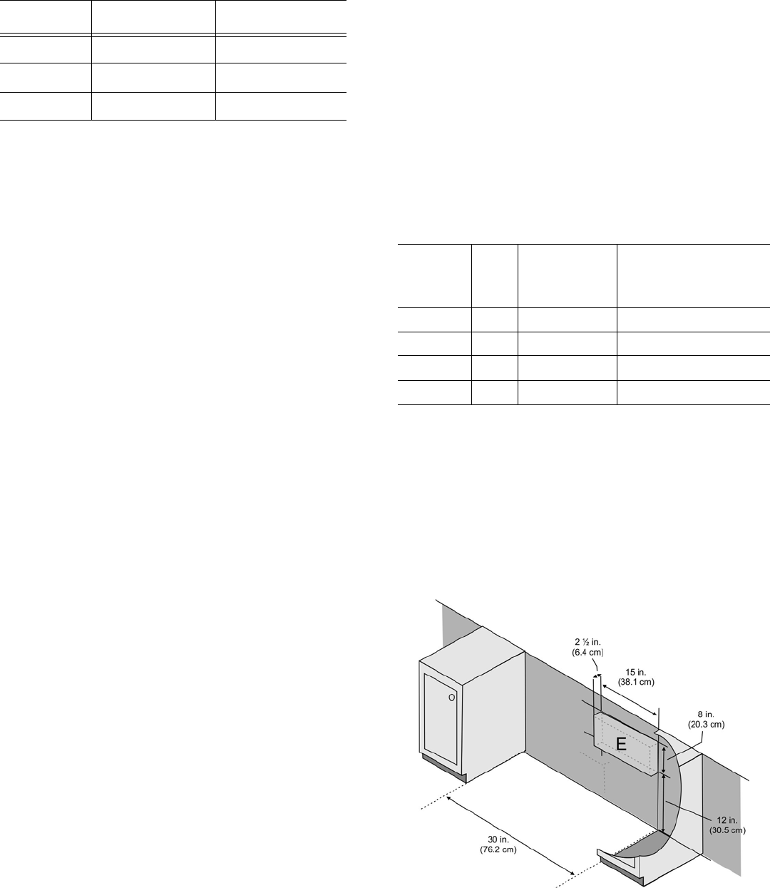
Emplacement de la prise électrique
Une prise encastrée avec circuit spécialisé de 208/240
VCA est requise. Utiliser le schéma ci-dessous pour vous
assurer que l'installation est correctement préparée pour la
cuisinière. Remarquez que l'espace disponible pour la
prise électrique est indiqué dans la boîte (E) de l'illustration
suivante.
Dimension Pouces Centimètres
Hauteur 36½” - 38” 927 mm - 966 mm
Largeur 31½” 800 mm
Profondeur 26¾” 681 mm
VOLTS
C/A
HZ RÉGIME
NOMINAL
KW
DISJONC-
TEUR
120/240 60 13.0 40 or 50 ampères*
120/240 60 13.8 40 or 50 ampères*
120/208 60 9.8 40 or 50 ampères*
120/208 60 10.4 40 or 50 ampères*