
Installation guide


D9412GV3/D7412GV3 | Operation and Installation Guide | 4.0 Installation
.
Bosch Security Systems, Inc. | 10/10 | F01U143070-03 14
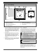
3.3.13 Ground Fault Detection Added Feature
When Ground Fault Detect is enabled (S4 closed),
Points 1 to 8 can be used for non-powered fire-
initiating devices such as heat detectors, four-wire
smoke detectors, and pull stations. A D125B Powered
Loop Interface or a D129 Dual Class A Interface
Module is not required when connecting the non-
powered fire-initiating devices to Points 1 to 8.
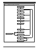
3.3.14 Conettix Functions
The D6600 Conettix System supports data network
communications. Conettix allows the D6600 Receiver
to connect to various network technologies including
Ethernet and GPRS (General Packet Radio System).
Connecting to a data network is possible using the
COM4 or COM1 connection from the D6600 Receiver
to the D6680 Network Adapter. Control panels can
send reports through telephone lines, Ethernet,
Token-Ring or GPRS networks to the D6600 receiver
at the central station. Once events are received, they
can then be issued to automation software or a
network printer through a local area network (LAN) or
wide area network (WAN).
Sending events to the central station over a LAN or
WAN requires a network interface module (NIM), such
as the DX4020. Sending events over GPRS requires
a special NIM, the ITS-DX4020-G.
3.3.15 Programming
Use the Remote Programming Software (RPS), or the
local Programmers Menu, to program the D9412GV3
and D7412GV3 Control Panels. Refer to the
D9412GV3/D7412GV3 Program Entry Guide (P/N:
F01U170807) for programming options.
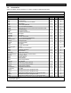
3.3.16 Other Features
D9412GV3 and D7412GV3 Control Panels have
many programmable features. Some of the features
are listed below. Complete details on all features are
in the D9412GV3/D7412GV3 Program Entry Guide
(P/N: F01U170807).
Supervision of AC (primary power), battery
(secondary power), Zonex and SDI buses, central
processing unit (CPU), up to three printers, and
two telephone lines
Automatic System Test Reports
Remote access for programming, diagnostics,
and log uploads using the remote programming
software (RPS)
Fire alarm verification
Programmable alarm output
Programmable relay output using the D8129
OctoRelay Module
Opening and closing windows
Skeds (scheduled events)
Limited local programming available in the
Service Menu
4.0 Installation
4.1 Installation Preparation
This section contains a general installation procedure
and refers to other sections of the document for
detailed instructions.
Review this document and the D9412GV3/D7412GV3
Program Entry Guide (P/N: F01U170807) before
beginning the installation to determine the hardware
and wiring requirements for the features used.
Have the following documentation available when
reading through this guide:
D9412GV3/D7412GV3 Program Record Sheet
(P/N: F01U170809)
Security System Owner’s Manual
(P/N: 71-06633-000) and GV3 Series Owner’s
Manual Supplement (P/N: F01U143082)
Installation manual for keypad or annunciator
(D1255 all models, D1255RB, D1256, D1256RB,
D1257, D1257RB, D1260 all models, or D720 all
models)
Before installation, become familiar with the operation
of RPS or the local Programmers menu.
4.2 Enclosure Options
Mount the control panel assembly in any of the Bosch
Security Systems, Inc. enclosures listed:
D8103 Universal Enclosure (tan)
D8109 Fire Enclosure (red)
D8108A Attack Resistant Enclosure (tan)
Refer to the D9412GV3/D7412GV3 Approved
Applications Compliance Guide (P/N: F01U143069) to
determine if the application requires a specific
enclosure.
4.3 Mounting Enclosure
1. Run the necessary wiring throughout the
premises.
2. Mount the enclosure in the desired location. Use
all five enclosure mounting holes. Refer to
Figure 2.
3. Pull the wires into the enclosure.
Electromagnetic interference (EMI) can
cause problems on long wire runs.