
Installation guide


D9412GV3/D7412GV3 | Operation and Installation Guide | 8.0 On-Board Points
.
Bosch Security Systems, Inc. | 10/10 | F01U143070-03 34
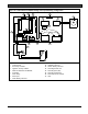
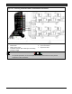
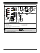
Figure 14: Rothenbuhler 5110/4001-42 High Security Bell Wiring Configuration
0.64 mm (1/4 in.)
minimum distance
+
-
+
-
17
3
14
16
15
4
7
5
8
12
13
1
1
11
11
9
2
6
10
10
1 - Self-contained vibration sensor
2 - Control panel
3 - Accessory modules
4 - High line security module
5 - 4001-42 Balanced Line Module
6 - 5110 Bell
7 - D133 Relay
8 - Zone input
9 - D122 Battery Harness*
10 - D126 Battery
11 - D8108A Enclosure
12 - D122L Battery Harness*
13 - Proximity/control unit
14 - Normally open (NO)
15 - Normally closed (NC)
16 - End-of-line (EOL) resistor
17 - Safe