
Installation Guide


English 8
Frontview cut out
Cleat
*
Suggested location of electrical outlet
**
Anti-Tip Block
***
Base should support up to 100 lbs
****
Sides should be finished and extend back to cleat.
Cleats should also be finished, as they may be
visible after installation.
(Cleats are not included with unit.)
*
**
****
A
B
C
D ***
E
G
H
I
J
P
P
M
K
L
O
N
F
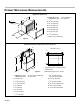
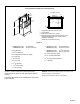
Flush Installation Dimensions and Clearances
Figure 4
Figures 2, 3 and 4 contain many Drawer Microwave
measurements for reference when planning the drawer’s
location.
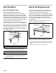
This Drawer Microwave can be installed below any electric
or gas wall oven.
NOTICE: Always allow sufcient power cord length to the
electrical outlet to prevent tension.
Always check electrical codes for requirements.
A.
HMD8451UC (24") 27" (686 mm)
HMD8053UC (30") 30
5
/16
" (770 mm)
B. 36" (914 mm)
C. 23
1
/2
" (597 mm)
D. 21
7
/8
" (555 mm) base min. depth
E. 4" (102 mm)
F. 6" (152 mm)
G. 5" (127 mm)
H. 3
1
/2
" (89 mm)
I. 14
5
/8
" (371 mm)
J. 1
5
/8
" (41 mm)
K. HMD8451UC (24") 22
1
/8
" (562 mm)
HMD8053UC (30") 28
5
/16
" (719 mm)
L. HMD8451UC (24") 24
3
/16
" (614 mm)
HMD8053UC (30") 30
5
/16
" (770 mm)
M. 16
5
/8
" (422 mm) cutout
N.
1
/2
" (13 mm) visible area
O.
1
/4
" (6 mm) base thickness
P. 1" (25 mm)