Household Appliances Over-the-Range Microwave Installation Instructions For Models: HMV9302, HMV9305, HMV9306, HMV9307 PLEASE READ ENTIRE INSTRUCTIONS BEFORE PROCEEDING IMPORTANT: Save these instructions for the local electrical inspector’s use. INSTALLER: Please leave these Installation Instructions with this unit for the owner. OWNER: Please retain these instructions for future reference.
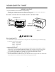
YOUR SAFETY FIRST BEFORE YOU START • Proper installation is the installer's responsibility! – Read the entire manual before you begin. The Model number label is located on the oven front. See Figure 1. Mounting plate is located on back side of microwave oven. See Figure 2. BE SURE TO READ THE FOLLOWING SAFETY INSTRUCTIONS: Model Number Label Mounting plate ( Remove from oven to install. ) Back of oven Figure 1 Figure 2 WARNING FOR YOUR SAFETY: • You will need TWO people to install this oven.
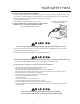
YOUR SAFETY FIRST • THIS APPLIANCE MUST BE GROUNDED! – If there is an electrical short circuit, grounding reduces the risk of electrical shock by providing an escape wire for the electric current. This appliance is equipped with a cord having a grounding wire with a grounding plug. • Place the plug into a properly installed and grounded outlet. See Figure 3. • Do not use an extension cord. • Keep the power cord dry and do not pinch or crush it.
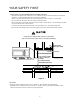
YOUR SAFETY FIRST • MAKE SURE YOU HAVE ENOUGH SPACE AND SUPPORT. – Mount the oven against a flat, vertical wall, so it is supported by the wall. The wall should be constructed of minimum 2" x 4" wood studding and 3/8" thick drywall or plaster/lath. – ATTACH AT LEAST ONE of the two lag screws supporting the oven to a vertical, 2" x 4" wall stud. – DO NOT mount the microwave oven to an island or peninsula cabinet. – BE SURE the upper cabinet and rear wall structures are able to support 150 lbs.
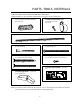
PARTS, TOOLS, MATERIALS THE FOLLOWING PARTS ARE SUPPLIED WITH THE OVEN: NOTE: Depending on your ventilation requirements, you may not use all of these parts.
PARTS, TOOLS, MATERIALS YOU WILL NEED THE FOLLOWING TOOLS AND MATERIALS FOR THE INSTALLATION: Carton or other heavy material for covering the counter top. Clear tape (for taping the templates to the wall) Stud finder or thin nail.
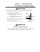
STEP 1: PREPARE THE ELECTRICAL CONNECTIONS WARNING AVOID ELECTRICAL SHOCK! THIS APPLIANCE MUST BE GROUNDED! 1. Locate the grounded electric outlet for this oven in the cabinet above the oven, as shown in Figure 4 Detail. NOTE: The outlet should be on a circuit dedicated to the microwave oven 120V, 60Hz., AC only with a 15 or 20A fused electrical supply. Upper Cabinet IMPORTANT: If you do not have the proper wall outlet, you MUST have one installed by a qualified electrician.
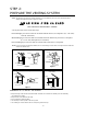
STEP 2: PREPARE THE VENTING SYSTEM NOTE: The ductwork you need for outside ventilation is not included with your oven. The standard ductwork fittings and length are shown in Figure 9, page 9. W A R N I N G : F I R E H A Z A R D THIS OVEN MUST BE PROPERLY VENTED! You may vent your oven in one of three ways: Roof-venting If your oven is located on an outside wall near the roof, as in Figures 5 (31/4" x 10" duct) and 8 (6" round duct.
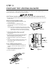
STEP 2: PREPARE THE VENTING SYSYTEM STANDARD FITTINGS NOTE: If the existing duct is round, you must use a rectangular-to-round adapter, with a rectangular 3" extension duct installed between the damper assembly and the adapter to prevent the exhaust damper’s sticking. DUCT LENGTH The total length of the duct system, including straight duct, elbows, transitions, wall or roof caps must not exceed the equivalent of 140 feet. For best performance, do not use more than three 90 degree elbows.
STEP 3: PREPARE THE VENTING BLOWER Your microwave oven is shipped with the blower assembled for roof venting. You need to adjust the blower if you want wall-venting or room-vented (recirculating) installation. WARNING ELECTRICAL SHOCK HAZARD! UNPLUG UNIT BEFORE WORKING ON IT. • DO NOT PULL OR STRETCH THE BLOWER WIRING! Pulling and stretching the blower wiring could result in electrical shock. REMOVE THE MOUNTING PLATE: 1. Remove any shipping materials and parts from inside the microwave oven. 2.
STEP 3: PREPARE THE VENTING BLOWER WALL-VENTED INSTALLATION: 1. Remove one blower unit mounting screw and one blower plate screw. Remove the blower plate from cabinet. See Figure 13. back plate blower unit blower plate mounting screws 2. Carefully lift the blower unit out of the microwave oven. 3. Use side cutters or tin snips to cut and remove knockouts “B” from Back plate. Discard knockouts. Be careful not to distort the plate. See Figure 14. Parts "B" blower unit mounting screw 4.
STEP 3: PREPARE THE VENTING BLOWER blower plate mounting screws exhaust ports blower unit exhaust ports Figure 17 blower unit mounting screws Figure 18 ROOM-VENTED (Recirculating) INSTALLATION: 1. Remove one blower unit mounting screw and one blower plate screw. Remove the blower plate from cabinet. See Figure 19. blower unit 2. Carefully lift the blower unit out of the microwave oven. blower plate mounting screws 3. Rotate blower unit 90˚ so the exhaust ports face the front of the cabinet.
STEP 4: PREPARE THE WALL AND UPPER CABINET FOR INSTALLATION MEASURE AND TACK / TAPE UP THE TEMPLATES 1. Using a plumb line and (metal) measuring tape, find and mark the vertical center line on the back wall, as in Figure 22. 2. Find and mark one or two points where the studs are on the wall (Studs are normally 16 inches apart) and then measure and mark the stud locations. If you cannot find any wall stud, consult a local building contractor.
STEP 4: PREPARE THE WALL AND UPPER CABINET FOR INSTALLATION DRILLING THE HOLES IN THE WALL AND UPPER CABINET: WARNING BE VERY CAREFUL WHEN DRILLING HOLES INTO THE WALL. Electrical wires could be concealed behind the wall covering and if the drill hits them you could get an electric shock. 1. Find the points on the mounting plate labeled A, B, C, and D. Drill a 3/16" diameter hole at any of these points that are in front of a wall stud.
STEP 5: INSTALL THE MOUNTING PLATE TO THE WALL CONNECTING THE OVEN TO A WALL STUD: NOTE: The oven must be connected to at least one wall stud. 3/16" Hole on Studs 3/4" Hole on Drywall Only Minimum 66" From the Floor 1. Draw a vertical line on the wall at the center of the 30″ wide space. For WallVented Only Use the mounting plate as the template for the rear wall. Place the mounting plate on the wall, making sure that the tabs are against the bottom of the cabinet.
STEP 5: INSTALL THE MOUNTING PLATE TO THE WALL TO PREPARE THE REAR WALL CUTOUT OPENING AND EXHAUST ADAPTOR/MOUNTING PLATE FOR WALL-VENTED: 1. Place the mounting plate against the rear wall as described in step 5 item 1 (page 15). 2. Using a pencil, put dots through slots F and G, and through holes H and I. Remove the mounting plate and draw lines extending through the points. This will give the location and size of the box cutout for the rear wall duct. See Figure 28.
STEP 6: ATTACH THE OVEN TO THE WALL WARNING power cord You will need two people to lift this microwave. Failure to use more than one person could result in personal injury. power cord hole 1. Carefully lift microwave oven and hang it on support tabs (See Figure 26 on the page 15) at the bottom of the mounting plate. Reaching through upper cabinet, thread power supply cord through the power supply cord hole in the bottom of the upper cabinet. See Figure 30. Figure 30 2.
STEP 6: ATTACH THE OVEN TO THE WALL 5. Roof vented installation: See Figure 32 Install ductwork through the vent opening in the upper cabinet. Complete the venting system through the roof according to the method needed. See “PREPARE THE VENTING SYSTEM,” step 2 on the page 8. Use caulking to seal exterior roof opening around the exhaust cap. See Figure 6 on page 8. damper Figure 32 6. Use power supply cord clamp to bundle the power supply cord.
Installation Notes
Printed in Korea P/No.