Easy Series (ICP-EZM2) Installer Guide EN Intrusion Control Panel
Easy Series (ICP-EZM2) | Installer Guide | Contents Contents 1.0 Quick Reference .................................................... 3 1.1 System Overview .................................................3 1.2 Control Center Overview ...................................3 1.3 Basic Operation Information..............................4 1.4 System Setup (Wired and Wireless) ..............5 1.5 Installer Phone Menu...........................................6 1.6 User Phone Menu .................................
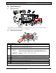
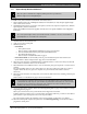
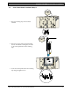
Easy Series (ICP-EZM2) | Installer Guide | 1.0 Quick Reference . 1.0 Quick Reference 1.1 System Overview C= C =12V C =0V 2 3 4 5 6 7 8 NC C NO 1 12 VDC 2 1 Connect either a two-wire smoke detector or an intrusion detector, such as a motion detector, to Point 1. 2 Use either the EZPS wire-in power supply or a transformer. 1.2 Control Center Overview 9 1 2 8 3 4 5 7 6 Callout 1 2 3 Description Press and hold [1] for two sec to start a fire alarm.
Easy Series (ICP-EZM2) | Installer Guide | 1.0 Quick Reference 1.3 Basic Operation Information Item Description House phone: Press [#] three times, and enter a passcode. Dial the house phone number, and press [*] three times when the call is answered. Enter a passcode. Connect a test telephone to the control panel’s test posts or telephone Installer quick connect: terminals. Press and hold the system test button for approximately 15 sec. Enter a passcode.
Easy Series (ICP-EZM2) | Installer Guide | 1.0 Quick Reference . 1.4 System Setup (Wired and Wireless) After the system is installed and configured, add key fobs when you add users. Wireless support is not investigated by UL. To install an Easy Series Intrusion Control Panel with wireless devices: 1. Follow all instructions in the wLSN Reference Guide (P/N: F01U009440) to verify adequate signal strength exists at each device location. 2.
Easy Series (ICP-EZM2) | Installer Guide | 1.0 Quick Reference 1.
Easy Series (ICP-EZM2) | Installer Guide | 1.0 Quick Reference . 1.6 User Phone Menu 1 Turn System On or Off Only use this option on non-UL systems. 2 Enter user passcode1 Two-Way Voice Session Phone Menu 1 Turn system on and stay inside 2 Turn system on and leave 3 Turn on custom protection # Exit To hear this option, custom protection must be enabled.
Easy Series (ICP-EZM2) | Installer Guide | 2.0 Installation 2.0 Installation Only use authorized service personnel to install this system. Because the control panel is permanently connected equipment, a readily accessible disconnect device must be included into the building installation wiring. Follow anti-static procedures when handling the control panel board. Touch the earth ground terminal on the control panel board to discharge any static charge before working on the control panel board.
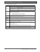
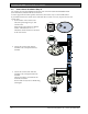
Easy Series (ICP-EZM2) | Installer Guide | 2.0 Installation . 2.2 Control Panel Board Installation (Step 2) 1. Place the mounting clips on the enclosure standoffs. 2. Place the top edge of the control panel board between the enclosure retaining slots, and then set the control panel board on the mounting clips. 3. Secure the control panel board to the mounting clips using the supplied screws. = Bosch Security Systems, Inc.
Easy Series (ICP-EZM2) | Installer Guide | 2.0 Installation 2.3 Control Center Installation (Step 3) For complete control center installation instructions, refer to the EZ1 Control Center Installation Guide (P/N: F01U003737) included with the control center. To ensure proper RF ID reader operation, mount the control center only on a non-metallic surface. If you install more than one control center, ensure that there is at least 1.2 m (4 ft) of space between each control center. 1.
Easy Series (ICP-EZM2) | Installer Guide | 2.0 Installation . CAT5 Cable Connections 1 7 + R Y G B 4 5 3 6 2 1234- Control center audio bus terminals Control center data bus terminals CAT5 cable Blue and blue-and-white-striped conductors (twisted pair) 8 5678- Bosch Security Systems, Inc.
Easy Series (ICP-EZM2) | Installer Guide | 2.0 Installation 2.4 DX2010 Installation (Step 4) The control panel supports up to three DX2010 Input Expanders for Points 9 to 32. Refer to the DX2010 Installation Instructions (P/N: 49533) for more information. 1. Mount the DX2010 into the control panel’s enclosure, or other suitable enclosure. = 102 2. Set the DX2010’s DIP switches. - Points 9 to 16 = Address 102 - Points 17 to 24 = Address 103 - Points 25 to 32 = Address 104 ON 103 OFF 104 3.
Easy Series (ICP-EZM2) | Installer Guide | 2.0 Installation . 2.5 Wireless Hub Installation (Step 5) Before installing the wireless hub or any wireless devices, refer to Section 3.0 Point Expansion on page 23, the ISW-BHB1-WX Installation Instructions (P/N: F01U500915), the wLSN Reference Guide (P/N: F01U009440), and the installation instructions supplied with each wireless device. 1. Perform a site test as described in the wLSN Reference Guide. 2.
Easy Series (ICP-EZM2) | Installer Guide | 2.0 Installation 2.6 Supervised Point Connections (Step 6) Separate primary AC power and standby battery wires from all power-limited wiring. Refer to Section 7.2 Power-limited Wire Routing on page 58 for more information. 2.6.1 Fire Point Wiring Supervised Point 1 supports two- and four-wire smoke detectors. Supervised Points 2 to 32 support only four-wire smoke detectors. To program supervised points as fire points, refer to Section 4.2.1 Points on page 31.
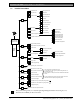
Easy Series (ICP-EZM2) | Installer Guide | 2.0 Installation . 2.6.2 Intrusion Point Wiring Refer to the figures below to wire Supervised Points 1 to 32 as wired or wireless intrusion points. To program Supervised Points 1 to 32 as intrusion points, refer to Section 4.2.1 Points on page 31. For fire point configuration, refer to Section 2.6.1 Fire Point Wiring on page 14. 1 1 1 5 2 5 4 4 6 3 4 2 Single 2.2 kΩ EOL resistor 1 - Supervised point (on-board, DX2010, or wireless input) 2 - 2.
Easy Series (ICP-EZM2) | Installer Guide | 2.0 Installation 2.7 Programmable Output Connections (Step 7) Separate primary AC power and standby battery wires from all power-limited wiring. Refer to Section 7.2 Power-limited Wire Routing on page 58 for more information. 2.7.
Easy Series (ICP-EZM2) | Installer Guide | 2.0 Installation . Dry Contact Option 1 2 3 (+) (-) 4 1234- 2.7.
Easy Series (ICP-EZM2) | Installer Guide | 2.0 Installation 2.8 Phone Line Connections (Step 8) Connect the incoming phone line and the house phone to the control panel board. 2.9 Insert Voice Module (Step 9) The voice module is required for system operation. 2.10 EZTS Connections (Step 10) If the optional EZTS Tamper Switch was installed in Step 1 on page 8, connect its cable to the two-pin connector on the control panel. 18 Bosch Security Systems, Inc.
Easy Series (ICP-EZM2) | Installer Guide | 2.0 Installation . 2.11 Power Supply Installation (Step 11) This system uses either the EZPS wire-in power supply, OR a plug-in power supply. Both power supplies require the enclosure ground wire and a standby battery. Follow the instructions below for the power supply used in your installation. The EZPS is not investigated by UL. 2.11.1 EZPS Wire-in Power Supply 1. Mount the EZPS on the enclosure using the screws supplied with the EZPS. 2.
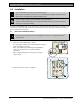
Easy Series (ICP-EZM2) | Installer Guide | 2.0 Installation 4. Connect the EZPS wires to the control panel board. 5. Insert the door hinges onto the enclosure. 6. Push the enclosure ground wire connector onto the unpainted part of the door’s top hinge. 5 7. Connect the enclosure ground wire to the threaded enclosure stud. 8. Connect the enclosure ground wire to the control panel board’s earth ground terminal. 6 8 7 EZPS 20 Bosch Security Systems, Inc.
Easy Series (ICP-EZM2) | Installer Guide | 2.0 Installation . 2.11.2 Plug-in Power Supply 1. Connect a ground wire from the enclosure to a good earth ground source. 2. Connect the enclosure ground wire. For instructions, refer to Steps 5 to 8 in Section 2.11.1 EZPS Wire-in Power Supply on page 19. 3. Connect the plug-in power supply to the control panel board. 3 2 1 2.11.3 12 VDC Standby Battery When all system wiring is complete, apply AC and standby battery power to the control panel.
Easy Series (ICP-EZM2) | Installer Guide | 2.0 Installation 2.12 Secure the Enclosure (Step 12) To secure the enclosure door: • Install the enclosure door lock, or • Secure the door with screws. Screws not supplied. OR 2.13 Program the Control Panel (Step 13) When installation is complete, you can program the control panel. Refer to Section 4.0 Programming on page 29 for more information. 2.14 Test the System (Step 14) When programming is complete, you must test the system for proper operation.
Easy Series (ICP-EZM2) | Installer Guide | 3.0 Point Expansion . 3.0 Point Expansion For complete wireless installation and configuration information, refer to the wLSN Reference Guide (P/N: F01U009440) supplied with the wireless hub, and the installation instructions supplied with each wireless device. Wireless support is not investigated by UL. 3.
Easy Series (ICP-EZM2) | Installer Guide | 3.0 Point Expansion 3.1.3 Configure Devices Input and Output Devices The ISW-BMC1-S135X Door/Window Contact and the ISW-BIN1-S135X Inertia Detector have a magnetic switch as an input. If the magnetic switch is not used, remove the magnet from the device before starting the Point Test. Once the network is established and configured, the system announces “Test all points.” Test the wireless devices in this order: input devices, output devices, and relay modules.
Easy Series (ICP-EZM2) | Installer Guide | 3.0 Point Expansion . Key Fobs Add key fobs after all other wireless devices (inputs and outputs) are discovered and configured. 1. After the last wireless device is configured and the Point Test ends, press [#] repeatedly until you exit the Installer Menu and end the phone session. 2. Start a new phone session, or press and hold [3] on the control center, and enter the master user (User 1) passcode. 3. Press [4] to select the User Menu. 4.
Easy Series (ICP-EZM2) | Installer Guide | 3.0 Point Expansion 3.2 Wireless Maintenance 3.2.1 Wireless Configuration Menu Use the Wireless Configuration Menu to: • Add new wireless devices to an existing wireless system • Add wireless devices that were not discovered when the wireless network was first discovered • Replace or delete wireless devices from an existing wireless system To access the Wireless Configuration menu: 1. Start a phone session. Refer to Section 1.
Easy Series (ICP-EZM2) | Installer Guide | 3.0 Point Expansion . 3.2.2 Assigning Points 1 to 8 as Wireless Points To assign an on-board point (1 to 8) as a wireless point, disable the point in programming before starting the device discovery process. You can individually assign Points 1 to 8 as wireless points. 3.2.3 DX2010 Input Expanders and Wireless Points If Points 9 to 32 contain wired and wireless points, install all required DX2010 Input Expanders before adding any wireless points to the system.
Easy Series (ICP-EZM2) | Installer Guide | 3.0 Point Expansion 3.3 Wireless System Messages Refer to the following table for a description of system messages that pertain to the wireless network. System Message “Wireless devices not configured.” “Extra device ignored.” “Point x was tested.” “Point x low.” “Please wait.” “Wireless error.” “Wireless devices x.” “Wireless devices not tested x.” “Point x not tested.” 28 Description Point Test was exited before all wireless points were tested.
Easy Series (ICP-EZM2) | Installer Guide | 4.0 Programming . 4.0 Programming 4.1 Enter Programming Select one of the following methods to enter the Installer Menu: Method House Phone Outside Phone Steps 1. Press [#][#][#]. 2. Listen for the voice prompt to enter a passcode. 3. Enter the installer passcode.1 4. Press [3] for basic programming, or [4] for expert programming. 1. Call the premises phone number. 2.
Easy Series (ICP-EZM2) | Installer Guide | 4.0 Programming 4.2 Basic Programming Basic programming consists of a voice menu that contains the essential programming items.
Easy Series (ICP-EZM2) | Installer Guide | 4.0 Programming . 4.2.1 Points You cannot program any wireless points without first completing the steps in Section 1.4 System Setup on page 5. Points Enter a point number from 1 to 32. 1 Record Point Description For example, if Point 1 is located at the building’s front door, say “Front Door” at the tone. Press [1] to continue programming the selected point. Press [2] to re-record your current point description.
Easy Series (ICP-EZM2) | Installer Guide | 4.0 Programming 4.2.2 Report Configuration Report Configuration [1] Account Number [2] Report Destination [1] Route 1 Primary [2] Route 1 Backup [3] Route 2 Primary [4] Route 2 Backup Format Format Format Format Phone Number Phone Number Phone Number Phone Number [#] Exit [#] Exit [#] Exit [#] Exit Route 1 Route 2 [#] Exit To configure reports: 1. 2. 3. 4. Enter a four- or six-digit account number.
Easy Series (ICP-EZM2) | Installer Guide | 4.0 Programming . 4.2.3 Outputs You cannot program any wireless outputs without first completing the steps in Section 1.4 System Setup on page 5 Output devices consist of horns, bells, or strobes. Outputs 1 Enter an output number from 1 to 8. Output Function Press [1] to select the current option. Press [2] to hear more options. Press [#] to exit Output Function.
Easy Series (ICP-EZM2) | Installer Guide | 4.0 Programming 4.2.4 Country Code Select the appropriate country code for your installation. This code sets the control panel to the appropriate country-specific defaults.
Easy Series (ICP-EZM2) | Installer Guide | 4.0 Programming . P T Country Pakistan Palau Panama Papua New Guinea Paraguay Peru Philippines Poland Portugal Principe Code 62 65 65 65 Country Taiwan Tajikistan Tanzania Thailand Togo Tonga Trinidad and Tobago Tunisia Turkey Turkmenistan Tuvalu 65 39 40 41 42 65 Q Country Qatar Code 62 Code 43 44 65 Country St. Kitts St. Lucia St.
Easy Series (ICP-EZM2) | Installer Guide | 4.0 Programming 4.3 Expert Programming Only use expert programming if you have a special programming requirement. To comply with specific agency requirements, refer to Section 7.7 Agency Approvals and Requirements on page 68 for any necessary programming changes.
Easy Series (ICP-EZM2) | Installer Guide | 4.0 Programming . 4.3.1 ROM Firmware Version Items Programming Item Control Panel Firmware Version Item Number 090 Control Center 1 Firmware Version Control Center 2 Firmware Version Control Center 3 Firmware Version Control Center 4 Firmware Version 091 092 093 094 4.3.2 Description System announces the installed firmware version. This item is read-only. System announces the installed firmware version for the selected control center.
Easy Series (ICP-EZM2) | Installer Guide | 4.0 Programming Programming Item Installer Passcode Override Enabled Item Number 122 Description (Range) Entry 0 = Override disabled 1 = Override enabled To override the installer passcode prompt, short solder pads together for approximately 5 sec (see below). 1 5s Programming Key Auto Transfer 123 Point Alarm Verification 124 Pick up phone to hear Installer Menu options. 0 = Installer must activate the programming key from the Installer Menu.
Easy Series (ICP-EZM2) | Installer Guide | 4.0 Programming . Programming Item Swinger Bypass Count Item Number 131 Description (Range) Entry 1 = One alarm report allowed from point while system is on before point is bypassed. 2 = Two alarm reports allowed from point while system is on before point is bypassed. 3 = Three alarm reports allowed from point while system is on before point is bypassed. 0 = System always turns on (unoccupied) when selected.
Easy Series (ICP-EZM2) | Installer Guide | 4.0 Programming Programming Item Test Report Hour Test Report Minute Test Report Day of Week Item Number 143 144 145 Test Report Day of Month 146 Restrict Confirmed Alarm Memory 147 Arming Beeps/Graduated Annunciation 148 Description (Range) Entry Enter the hour that the control panel sends the test report (0 to 23). Enter the minute that the control panel sends the test report (0 to 59). Select the day that the control panel sends the test report.
Easy Series (ICP-EZM2) | Installer Guide | 4.0 Programming . 4.3.
Easy Series (ICP-EZM2) | Installer Guide | 4.0 Programming Programming Item Call Waiting Disable Item Number 215 Description (Range) Entry Enter a 3-digit string. Dial this first before dialing the premises phone number. * = [*][*]; # = [*][#] Dialing a call waiting sequence on a non-call waiting phone line prevents the system from successfully contacting the central station. 0 Enter a 3-digit emergency number, such as 911.
Easy Series (ICP-EZM2) | Installer Guide | 4.0 Programming . 4.3.
Easy Series (ICP-EZM2) | Installer Guide | 4.
Easy Series (ICP-EZM2) | Installer Guide | 4.0 Programming .
Easy Series (ICP-EZM2) | Installer Guide | 4.0 Programming 4.3.5 Point Programming Items Refer to the Point Programming Entry Tables, starting on page 47, for expert programming item numbers, default values, and programming entry cells. Programming Item Point Type Circuit Style Include in Custom Protection Cross Zone Enabled Description (Range) Refer to Section 4.2.1 Points on page 31 for point type descriptions.
Easy Series (ICP-EZM2) | Installer Guide | 4.
Entry Programming Item (Item Number) Entry Point Type (9091) 0 Point Type (9131) 0 Circuit Style (9092) 2 Circuit Style (9132) 2 Include in Custom Protection (9093) 0 Include in Custom Protection (9133) 0 Cross Zone Enabled (9094) 1 Cross Zone Enabled (9134) 1 Wireless Detector Sensitivity (9098) Voice Description 0 Wireless Detector Sensitivity (9138) Voice Description 0 Point 9 Wired Wireless Wired Wireless Entry Programming Item (Item Number) Entry Point Type (9101) 0 Point
Easy Series (ICP-EZM2) | Installer Guide | 4.
Entry Programming Item (Item Number) Entry Point Type (9251) 0 Point Type (9291) 0 Circuit Style (9252) 2 Circuit Style (9292) 2 Include in Custom Protection (9253) 0 Include in Custom Protection (9293) 0 Cross Zone Enabled (9254) 1 Cross Zone Enabled (9294) 1 Wireless Detector Sensitivity (9258) Voice Description 0 Point 25 Wireless Detector Sensitivity (9298) Voice Description 0 Point 29 Wired Wireless Entry Programming Item (Item Number) Entry Point Type (9261) 0 Point Type (9
Easy Series (ICP-EZM2) | Installer Guide | 4.0 Programming . 4.3.6 Output Programming Items Use Outputs 5 to 8 only for wireless output devices. Programming Item Fire Output Cadence Item Number 600 Description Entry 0 = Temporal Code 3 cadence 0 1 = Pulse cadence (two-sec on, two-sec off) Output 1 Type Output 2 Type Output 3 Type Output 4 Type Supervised speaker driver option. Refer to Expert Programming Item Number 642.
Easy Series (ICP-EZM2) | Installer Guide | 4.0 Programming 4.3.7 Control Center Programming Items Speech Configuration Items Programming Item Alarm Message Minimum Repeat Time Item Number 880 Description (Range) Entry Enter how long the control center waits between alarm message announcements before repeating the message even if the control center’s proximity sensor detects motion (1 to 255 hrs). 0 = No announcement for aborted alarms.
Easy Series (ICP-EZM2) | Installer Guide | 4.0 Programming . Individual Control Center Items These programming items are set independently for each control center connected to the control panel. Programming Item Control Center Brightness Control Center Backlight Extinguish Mode Default 4.3.
Easy Series (ICP-EZM2) | Installer Guide | 4.0 Programming 4.5 1. Programming Key If the system is on, turn it off. OR 2. Place the key’s lock switch in the desired position. Send data from control panel to key. Send data from key to control panel. Verify the switch position before inserting the programming key into the control panel board. An incorrect switch position might overwrite programming data. 3. Insert the key into the control panel board.
Easy Series (ICP-EZM2) | Installer Guide | 4.0 Programming . 4.6 Remote Programming Software (RPS) There are two methods to start a session with the remote programming software (RPS): the installer calls RPS, or RPS calls the control panel. Select the method that best meets the system’s needs for remote programming. RPS-to-control panel communication not investigated by UL.
Easy Series (ICP-EZM2) | Installer Guide | 5.0 System Test 5.0 System Test When the installation and programming of the control panel is complete, test the control panel and all devices for proper operation. Test the control panel after you first program it, and after any subsequent programming. If you test a device and the control panel does not respond, check the device, its wiring, and any related settings or programming for potential errors.
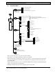
Easy Series (ICP-EZM2) | Installer Guide | 7.0 Reference Materials . 7.0 Reference Materials 7.1 Enclosure Wiring Label IUI-EZ1 Control Center Audio Bus (+) Audio Bus (-) Twisted pair wire (recommended) Test posts for phone set connection ICP-EZM2 Control Panel BGY R Current Draw: Voltage: Total Alarm Power: Auxiliary Power Current: * 3 m (10 ft) minimum distance from control panel to control center 85 mA standby; 160 mA alarm (all outputs activated) 12.0 VDC nominal (11.2 VDC to 12.3 VDC)* 1.
Easy Series (ICP-EZM2) | Installer Guide | 7.0 Reference Materials 7.2 Power-limited Wire Routing All wiring except primary AC power and standby battery is power-limited. Separate primary AC power and standby battery wires from other wires by at least 6.4 mm (¼ in.), and secure to enclosure to prevent movement. Primary AC power and standby battery wiring cannot share the same conduit, conduit fittings, or conduit knockouts with any other wiring. 1 6.4 mm (¼ in.) 2 6.4 mm (¼ in.
Easy Series (ICP-EZM2) | Installer Guide | 7.0 Reference Materials . 7.3 Standby Battery Calculation Use the following formula to calculate standby battery capacity for 24 hr of standby power and 4 to 30 minutes of alarm power: (Total B _____ x 24 hr) + (Total C _____ x Y hr*) + 10% reserve = Total battery Ah required * Y hr = - For UL-approved residential applications (household), Y = 0.067 (4 minutes) - For UL-approved commercial applications, Y = 0.
Easy Series (ICP-EZM2) | Installer Guide | 7.0 Reference Materials 7.
Easy Series (ICP-EZM2) | Installer Guide | 7.0 Reference Materials .
Easy Series (ICP-EZM2) | Installer Guide | 7.0 Reference Materials 7.5 Display States Display Color Description Green circle No alarm or trouble conditions exist. You can turn on the system. Flashing green circle Flashing amber circle Broken green circle System Off Broken amber circle 62 System trouble exists. You can still turn on the system. Alarm memory active. System trouble exists. You cannot turn on the system. Alarm memory active. Wired point(s) are faulted.
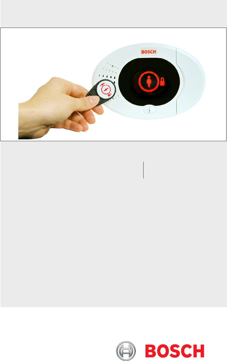
Easy Series (ICP-EZM2) | Installer Guide | 7.0 Reference Materials . System On (Unoccupied) System On (Occupied or Custom Protection) Display Color Description Flashing red icon Exit Delay in progress. Circle segments turn on, one at a time, to provide a visual status of Exit Delay. Red System is on (occupied or custom protection). Flashing icon (amber then red) Entry Delay in progress. Circle segments turn off, one at a time, to provide a visual status of Entry Delay.
Easy Series (ICP-EZM2) | Installer Guide | 7.0 Reference Materials 7.6 Frequently Asked Questions (FAQ) 7.6.1 Programming Questions Can I program the control panel if I do not have a phone line connected to it? Yes. Follow these steps: 1. Connect a phone set to the phone set posts on the control panel board. 2. Press and hold the system test button for approximately 15 sec. 3. Enter the installer passcode when prompted. The emergency buttons on the control center do not work.
Easy Series (ICP-EZM2) | Installer Guide | 7.0 Reference Materials . I want to use the Custom Protection feature. How do I turn it on? Follow these steps: 1. Start a phone session. Refer to Section 1.3 Basic Operation Information on page 4 for instructions. 2. Enter the installer passcode. 3. Press [4] to select Expert Programming. 4. Enter the appropriate expert programming item number. Use Expert Programming Item Numbers 9013 to 9323 to set the Custom Protection option for each desired point.
Easy Series (ICP-EZM2) | Installer Guide | 7.0 Reference Materials How do I delete a user? Only the master user can delete a user. From the control center: 1. Press and hold [3]. 2. When prompted, present the master user token or enter the master user passcode. 3. Press [3] to delete a user. 4. To select the first available user (not the master user), press [1]. To select a different user, press [2]. Repeat this step until you select the desired user. 5. Press [1] to delete the user.
Easy Series (ICP-EZM2) | Installer Guide | 7.0 Reference Materials . 7.6.3 Control Center Questions How do I set the control center’s address? On the control center’s printed circuit board, turn the rotary switch to the desired position (1 to 4). Each control center must have a unique address. The control center does not initialize. All I see is a flashing amber circle. Ensure that the rotary address switch on the control center’s printed circuit board is properly set and not halfway between two numbers.
Easy Series (ICP-EZM2) | Installer Guide | 7.0 Reference Materials 7.7 Agency Approvals and Requirements 7.7.1 Certifications and Approvals Compliance with specific standards, such as SIA CP-01 and DD243, reduces false alarms and is required in many locations.
Easy Series (ICP-EZM2) | Installer Guide | 7.0 Reference Materials . Part 68 This equipment complies with Part 68 of FCC rules. A label contains, among other information, the FCC registration number and ringer equivalency number (REN). If requested, this information must be provided to the telephone company. The Bosch Security Systems Easy Series Intrusion Control Panel is registered for connection to the public telephone network using an RJ38X or RJ31X jack.
Easy Series (ICP-EZM2) | Installer Guide | 7.0 Reference Materials Quick Reference Refer to the following table for programmable features, shipping defaults, and recommended programming that comply with the ANSI/SIA CP-01 False Alarm Reduction standard. The system test button tests all points, all outputs, the control panel, and the communicator. Refer to Section 5.0 System Test on page 56 for more information. Paragraph Number in ANSI/SIA CP-01 4.2.2.1 4.2.2.2 4.2.2.3 4.2.2.5 4.2.4.4 4.2.3.1 4.2.5.
Easy Series (ICP-EZM2) | Installer Guide | 7.0 Reference Materials . 7.7.5 Underwriters Laboratories (UL) Household Fire Warning System • Install at least one UL Listed four-wire latching type smoke detector rated to operate over the voltage • • • • • range of 11.2 VDC to 12.3 VDC. The maximum smoke detector load is 50 mA. Install one UL Listed 85 dB audible device rated to operate over the range of 11.2 VDC to 12.3 VDC as required for this application.
Easy Series (ICP-EZM2) | Installer Guide | 7.0 Reference Materials 7.7.6 EN50131-1 The Easy Series Intrusion Control Panel is designed to comply with EN50131-1 Security Grade 2, Environmental Class II. Installation, Programming, and Maintenance • Installation: Refer to Section 2.0 Installation on page 8. • Programming: Refer to Section 4.0 Programming on page 29. • Testing: Refer to Section 5.0 System Test on page 56. • Maintenance: Refer to Section 6.0 Maintenance on page 56.
Easy Series (ICP-EZM2) | Installer Guide | 7.0 Reference Materials . 7.7.7 PD6662 and DD243 Requirements To comply with PD6662 and DD243, you must meet all of the EN50131-3 requirements and the following requirements: Maintenance A qualified technician must check the system at least twice a year. AC Power Supply • Type: A • Rated Voltage: 230 V • Rated Input Frequency: 50 Hz • Rated Input Current: 250 mA maximum • Fuse Rating: 0.
Easy Series (ICP-EZM2) | Installer Guide | 7.0 Reference Materials 7.
Easy Series (ICP-EZM2) | Installer Guide | 7.0 Reference Materials . Phone Line Phone line trouble voltage: Trouble condition occurs when the phone line voltage is between 1.10 V and 4.75 V Control Panel Power Requirements AC Input Line Voltage Use a UL Listed 18 V Class 2 transformer (22 VAC, VA 50/60 Hz), or the EZPS Power Supply (not investigated by UL). Total Alarm Power: 1.4 A (AC power and standby battery; intrusion applications only). With a 7.
Easy Series (ICP-EZM2) | Installer Guide | 7.0 Reference Materials Wireless Hub (ISW-BHB1-WX) Wire Gauge: Power/Voltage: Wire Length: Compliance: 7.9 Compatible Options Model Number C900V2 CX4010 D132A DX2010 ICP-EZPK ICP-EZPS* ICP-EZPS-FRA* ICP-EZRU2 ICP-EZTS ICP-TR1822-CAN ISW-BHB1-WX* ITS-300GSM* IUI-EZ1 IUI-EZT-5 RPS-INTL* TF008* 0.14 mm (#18 AWG) to 1.
Easy Series (ICP-EZM2) | Installer Guide | Index . Index A E Account Number.......................................................................41 Arming Beeps............................................................................40 Auto Detect Pulse Dial ............................................................42 Auto Protection Level ..............................................................39 Emergency Call Override Number .......................................
Easy Series (ICP-EZM2) | Installer Guide | Index P R Passcode Control Center Lockout Time ...........................................52 Installer Passcode ...............................................................53 Installer Passcode Override Enabled .............................38 Invalid Passcode Attempt Limit ........................................52 Master User Passcode .......................................................53 Passcode Length.....................................................
Easy Series (ICP-EZM2) | Installer Guide | Index V W Voice Format Message Delivery Attempts ..............................................41 Repeat Count .......................................................................41 Voice Module Installation..............................................................................18 Wireless Assigning Points 1 to 8 As Wireless Points.................27 Configuration Menu.............................................................23 Device Configuration .
Bosch Security Systems, Inc. www.boschsecuritysystems.com © 2006 Bosch Security Systems, Inc.