ICP-VR8488 Quick Reference Guide EN Intruder Alarm System
ICP-VR8488 | Quick Reference Guide | EN | 2 Copyright Notice Notice of Liability Unless otherwise indicated, this publication is the copyright of Bosch Security Systems, Inc. (“Bosch”). All rights are reserved. This material is designed for use by tradespeople with expertise in the installation of this product. Persons without appropriate expertise should seek assistance before attempting installation. You may download a single copy of this publication.
ICP-VR8488 | Quick Reference Guide | Contents 1.0 Product Contents.............................................. 6 2.0 2.1 Introduction ...................................................... 6 Features ............................................................. 6 3.0 Installation......................................................... 6 4.0 4.1 4.2 RF Receiver Interface Connections ............... 9 Wiring and Power Up...................................... 9 Operation ............................
ICP-VR8488 | Quick Reference Guide | Zone Status – Zone Tamper Report...........................21 Zone Status – Walk Test Report.................................21 Zone Status – Bypass Report.......................................21 Zone Status – Trouble Report.....................................21 Zone Status – Sensor Watch Report...........................21 Zone Status – Alarm Restore Code ............................21 Zone Status Reporting Options...................................
ICP-VR8488 | Quick Reference Guide | Tables Table 1: Table 2: Table 3: Table 4: Table 5: Keypad Indicator States .........................12 Location 177 Programming Option Bits14 Telephone Monitor Mode Zone LEDs.15 Fault Indicators........................................16 Hexadecimal Values for Zone Nos. ......27 Bosch Security Systems, Inc.
ICP-VR8488 | Quick Reference Guide | 1.0 Product Contents Figure 1: EN | 6 Opening the Cover 1.0 Product Contents The Bosch Security Systems, Inc. (Bosch) ICP-VR8488 Intruder Alarm System includes: ICP-VR8488 unit (includes case, keypad, ICP-VR8488 printed circuit board, 433MHz RF Receiver (RF3213E) 2.0 Introduction The ICP-VR8488 is a desktop alarm system that incorporates keyfobs and supervised wireless sensors. You can assign up to 16 separate wireless devices to any of the eight available zones. 2.
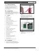
ICP-VR8488 | Quick Reference Guide | 3.0 Figure 3: Installation RF Receiver Data Cable EN | 7 Figure 5: Removing the DC Siren and ICP-VR8488 PCB 1 1 1 – RF Receiver data cable connector 6. Remove the RF Receiver from the case by pressing the two holding clips away from the RF Receiver while lifting the RF receiver circuit board away from the clips. Refer to Figure 4 on page 7. Figure 4: Removing the RF Receiver 1 3 2 1 – Siren latch 2 – ICP-VR8488 PCB latch 3 – DC siren 8.
ICP-VR8488 | Quick Reference Guide | 3.0 Figure 7: Installation Telephone Lead EN | 8 Figure 9: Rubber Feet Locations 1 1 – Telephone lead 10. Push the AC MAINS lead through the hole as shown in Figure 6 on page 7. If you are mounting the ICP-VR8488 on the wall, do Step 11. If not, do Step 12. 11. Mount the ICP-VR8488 on a suitable location using the four screw holes located in the base of the ICP-VR8488 case as shown in Figure 8 on page 8. Figure 8: 1 – Rubber feet 13.
ICP-VR8488 | Quick Reference Guide | 4.0 Figure 11: RF Receiver Interface Connections Connecting the AC Plug Pack EN | 9 4.0 RF Receiver Interface Connections Figure 13: RF Receiver (RF 3213/E) Wiring Diagram 1 2 1 – ICP-CC488 Control Panel 2 – RF Receiver (RF 3213/E) 4.1 2 1 1 – AC power connections 2 – AC plug pack leads 17. Insert the 12 VDC 2 A battery (refer to Figure 12 on page 9). Figure 12: Installing the Battery 1. 2. 3. 4.2 Wiring and Power Up Remove power from the control panel.
ICP-VR8488 | Quick Reference Guide | 5.0 Diagrams EN | 10 5.0 Diagrams Figure 14: Wiring Diagram 1 – 605 plug 2 – 6 (Red) Telecom line (street) 5 (Yellow) Internal phone line 3 and 4 Not used 2 (Black) Telecom line (street) 1 (Green) Internal phone line 3 – Zone 1 4 – Zone 5 5 – Zone 2 6 – Zone 6 7 – Power to external equipment: 12 V @ 400 mA 8 – PIR 9 – Zone 8 10 – Zone 4 11 – Zone 7 12 – Zone 3 13 – Piezo siren 14 – Smoke detector Bosch Security Systems, Inc.
ICP-VR8488 | Quick Reference Guide | 5.0 Diagrams EN | 11 Figure 15: ICP-CC488 Component Overlay 1 – Socket for telecom lead connect 2 – Termination for phone line OUT – internal phone line IN – Telecom line (street) 3 – Receiver interface connection 4 – Zone termination strip 5 – Output termination strip Bosch Security Systems, Inc.
ICP-VR8488 | Quick Reference Guide | 6.0 Getting to Know the ICP-VR8488 6.0 Getting to Know the ICP-VR8488 The ICP-VR8488 Intruder Alarm System is made up of a control panel and detection devices such as magnetic/motion sensors and smoke sensors. The user operates the ICP-VR8488 using either the keypad or RF keyfobs. If a detection device detects intrusion or smoke, the status of the device changes from normal to faulted.
ICP-VR8488 | Quick Reference Guide | 7.0 6.5 Programming the System STAY Indicator Figure 17: RF333: 4-Button Keyfob Transmitter The STAY indicator lights when the ICP-VR8488 is turned on in STAY Mode. 6.6 EN | 13 5 1 Trouble Conditions and the Service Indicator 2 The keypad beeps once every min to warn you of the trouble condition. Press [#] once to acknowledge the trouble condition and stop the keypad beeping. 6.
ICP-VR8488 | Quick Reference Guide | 8.0 Using the System EN | 14 Example 8.2 To program Phone Number 1 for Destination 1 as 96721233 and the Account Number for Destination 1 as 9876: 1. Enter the Installer Code and press [#] to enter Installer’s Programming Mode. For example, [1 2 3 4 #]. 2. Enter [0 #] to move to Location 000. 3. Enter: [9 * # 6 * # 7 * # 2 * # 1 * # 2 * # 3 * # 3 *] to program Phone Number 1 for Destination 1 as 96721233. 4. Enter [3 4 #] to go to Location 034. 5.
ICP-VR8488 | Quick Reference Guide | 8.0 8.6.2 Using the System STAY Mode 1 Press and hold [*] until two beeps sound. Or Enter your code and press [*]. For example, [2 5 8 0 *]. 8.6.3 STAY Mode 2 2. 3. EN | 15 To send a Test Report, press and hold [9] until two beeps sound. When complete, repeat Step 1 to toggle Telephone Monitor Mode off. Table 3: Telephone Monitor Mode Zone LEDs Press and hold [0] until two beeps sound. 8.
ICP-VR8488 | Quick Reference Guide | 8.0 8.18 Using the System 3. Toggle Day Alarm On/Off Press and hold [4] until two beeps sound. Day Alarm toggles on or off. 8.19 1. 2. 4. STAY Mode 2 Zones - Program Enter the Installer Code or your Master Code and press [4 #]. For example, [1 2 3 4 4 #]. Enter the zone number the system should automatically isolate and press [*]. Table 4: Zone Indicator 1 2 3 4 5 6 8.
ICP-VR8488 | Quick Reference Guide | 9.0 Programming Guide 9.0 Programming Guide Shaded options indicate default values.
ICP-VR8488 | Quick Reference Guide | 9.0 Programming Guide Telephone Line Fail Options 176 Location 0 Default 1 Display FAULT indicator when telephone line fails 2 Sound alarm when system arms 4 Sound alarm when system disarms Options 2 and 4 must be used in conjunction with Option 1 (for example, program 1, 3, 5, or 7).
ICP-VR8488 | Quick Reference Guide | 9.
ICP-VR8488 | Quick Reference Guide | 9.0 Programming Guide 309 to 322 (continued) Location Zone Options 1 Zone #07 (Default = Instant) Zone Type 309 Zone Pulse Count 310 Zone Pulse Count Time 311 Zone Options 1 312 Zone Options 2 313 Report Code 314 Dialer Options 315 Zone #08 (Default = 24 hr.
ICP-VR8488 | Quick Reference Guide | 9.
ICP-VR8488 | Quick Reference Guide | 9.
ICP-VR8488 | Quick Reference Guide | 9.
ICP-VR8488 | Quick Reference Guide | 9.0 Programming Guide Event Codes (continued) 3 3 3 3 3 3 3 3 3 3 3 3 4 4 4 4 4 4 4 4 4 4 4 4 4 4 4 4 5 5 5 5 5 5 5 5 5 5 5 5 5 5 5 5 6 6 Event Code 4 5 6 7 8 9 10 11 12 13 14 15 0 1 2 3 4 5 6 7 8 9 10 11 12 13 14 15 0 1 2 3 4 5 6 7 8 9 10 11 12 13 14 15 0 1 Description Codepad Panic (multibreak) v1.
ICP-VR8488 | Quick Reference Guide | 9.
ICP-VR8488 | Quick Reference Guide | 9.
ICP-VR8488 | Quick Reference Guide | 9.
ICP-VR8488 | Quick Reference Guide | 10.0 Country Codes EN | 28 10.0 Country Codes Country Code Country Code Country Code Country Code Country Code Argentina 01 Poland 41 Liechtenstein 63 Gabon 65 Papua New Guinea 65 Gambia 65 Paraguay 65 Ghana 65 Rwanda 65 65 St.
ICP-VR8488 | Quick Reference Guide | 10.0 Country Codes EN | 29 Country Code Country Code Country Code Country Code Nigeria 37 French Polynesia 63 Equatorial G uinea 65 Nicaragua 65 65 Norway 38 Iceland 63 Eritrea 65 Niger Peru 39 Israel 63 Ethiopia 65 Palau 65 Philippines 40 Lebanon 63 Fiji 65 Panama 65 Bosch Security Systems, Inc.
ICP-VR8488 | Quick Reference Guide | Notes EN | 30 Notes Bosch Security Systems, Inc.
ICP-VR8488 | Quick Reference Guide | Notes EN | 31 Notes Bosch Security Systems, Inc.
Bosch Security Systems, Inc. 130 Perinton Parkway Fairport, NY 14450-9199 USA www.boschsecurity.com © 2008 Bosch Security Systems, Inc.