wireless Local SecurityNetwork Reference Guide EN wLSN
wLSN | Reference Guide | Trademarks Trademarks Pet Friendly® is a registered trademark of Bosch Security Systems in the United States. 2 Bosch Security Systems, Inc.
wLSN| Reference Guide | Contents Contents 1.0 Using this Document ..........................................................7 2.0 2.1 2.2 2.3 2.4 2.5 2.6 General Installation............................................................9 Installation Considerations........................................................ 9 General Specifications .............................................................. 9 Installation Procedure .............................................................
wLSN | Reference Guide | Contents 9.0 9.1 9.2 wLSN Inertia Detector .............................................36 Sensitivity Settings.................................................................. 37 Test Mode............................................................................... 38 10.0 10.1 10.2 wLSN Key Fob........................................................39 Key Fob Buttons ..................................................................... 40 LED................................
wLSN| Reference Guide | Figures Figures Figure 1: Figure 2: Figure 3: Figure 4: Figure 5: Figure 6: Figure 7: Figure 8: Figure 9: Figure 10: Figure 11: Figure 12: Figure 13: Figure 14: Figure 15: Figure 16: Figure 17: Figure 18: Figure 19: Figure 20: Figure 21: Figure 22: Device Tamper Switches.................................................. 13 wLSN Installation Tool...................................................... 22 Switches.........................................................................
wLSN | Reference Guide | Tables Tables Table 1: Table 2: Table 3: Table 4: Table 5: Table 6: Table 7: Table 8: Table 9: Table 10: Table 11: Table 12: Table 13: Table 14: Table 15: Table 16: Table 17: Table 18: Table 19: Table 20: Table 21: Table 22: Table 23: Table 24: 6 wLSN Products and Instructions......................................... 8 General Specifications........................................................ 9 LED Flash Patterns in RFSS Mode ..................................
wLSN | Reference Guide | 1.0 Using this Document 1.0 Using this Document This document contains the basic information that a trained installer needs to install the wireless Local SecurityNetwork (wLSN). It supplements the documents listed in Table 1 on page 8. This reference guide contains: • A description of the wLSN general installation procedure (Section 2.0 General Installation on page 9). • Device-specific installation procedures (Sections 3.0 through 14.0 starting on page 21).
wLSN | Reference Guide | 1.
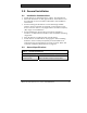
wLSN | Reference Guide | 2.0 General Installation 2.0 General Installation 2.1 • • • • • • Installation Considerations wLSN devices are intended only for indoor, dry applications. Mount wLSN devices on flat, rigid surfaces. Some devices can be optionally corner mounted as indicated in the installation instructions. Avoid mounting wLSN devices in areas with large metallic objects, electrical panels (for example: control panel or fuse box) or electric motors.
wLSN | Reference Guide | 2.0 General Installation 2.3 Installation Procedure When installing a wLSN Network, you must plan your installation based on the control panel and wLSN specifications, and the radio-frequency signal strength (RFSS) between remote devices and the wLSN Hub. The wLSN installation procedure consists of two parts: 1. Site testing for radio-frequency signal strength (RFSS) between remote devices and the wLSN Hub. 2. Mounting all wLSN devices.
wLSN | Reference Guide | 2.0 General Installation 2.4 Site Testing (RFSS Mode) Before permanently installing any wLSN device, verify that the radio-frequency signal strength (RFSS) between the planned device location and the planned wLSN Hub location is acceptable. CAUTION: If you have wireless devices that you will not immediately install, reinsert the battery tabs or remove the batteries to prevent battery depletion.
wLSN | Reference Guide | 2.0 General Installation You must test the devices at the same EN50131 Security Grade at which the control panel discovers the devices. 4. Find a suitable location for the hub base and apply power by either connecting it to the control panel (refer to the control panel’s installation instructions), or temporarily connecting a 9 VDC to 12 VDC battery. 5. Insert the wLSN Hub back into the base. Rotate the enclosure locking mechanism to the locked position. 6.
wLSN | Reference Guide | 2.0 General Installation Figure 1: Device Tamper Switches 2 1 1- Button style tamper switch 2- Lever style tamper switch 3. Hold the device at the planned mounting location. 4. Determine if the RF signal strength is acceptable by observing the device’s LED flash pattern (Table 3). The flash pattern appears for 10 min. Table 3: LED Flash Patterns in RFSS Mode LED Flash Pattern Flashes at 1 sec intervals Flashes rapidly (0.
wLSN | Reference Guide | 2.0 General Installation Reset the wLSN Hub’s DIP switches to their original settings to exit RFSS mode. Refer to Section 2.4.1 Preparing the wLSN Hub for Site Testing and RFSS Mode on page 11. To cause a device to exit RFSS mode, remove the device's batteries and re-insert them. Devices automatically exit RFSS mode after 10 min of inactivity. 2.4.
wLSN | Reference Guide | 2.0 General Installation 4. Hold the Installation Tool at the device’s planned mounting location. Use Mode 1 to determine if the signal strength is acceptable or not. Modes 2 and 3 help you determine how acceptable the signal strength is. Use Modes 2 and 3 to place the wLSN Hub and device in the best signal strength locations. Refer to Mode 1, Mode 2 (page 16), and Mode 3 (page 17) for more information on acceptable signal strength levels.
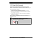
wLSN | Reference Guide | 2.0 General Installation Mode 2 Select Mode 2 by pressing [2]. The Mode 2 display shows power bars on the left and PACKETS = X on the right. The bars indicate the signal strength. More solid bars indicate a stronger signal. The Installation Tool shows the number of packets received: 1, 2, or 3. The best location for placing the device is the one that shows the highest number of solid bars with the highest number of packets.
wLSN | Reference Guide | 2.0 General Installation Mode 3 Select Mode 3 by pressing [3]. M O D E S N R y 3 y : S x x x d B m N x x x d B m The Mode 3 display shows the signal to noise ratio (SNR) at the location you are testing. Signal refers to the signal strength of the incoming message from the wLSN Hub to the Installation Tool. Noise refers to the ambient noise level that exists at the location. The signal must be greater than the noise (S>N).
wLSN | Reference Guide | 2.0 General Installation 2.5 Defaulting a wLSN Device (Undiscovered State) Discovery is the process through which the wLSN Hub identifies and includes new devices into a system. Only undiscovered devices can be placed in RFSS mode. To ensure a device is undiscovered: 1. Remove the batteries. 2. Press and hold the tamper switch button. Refer to Figure 1 on page 13. 3. Reinsert the batteries while holding the tamper switch button. The device’s LED turns on. 4.
wLSN | Reference Guide | 2.0 General Installation 2.6 Battery Requirements Dispose of used batteries according to manufacturer’s instructions. When you insert batteries into a wireless device, the LED turns on for approximately five sec to indicate that battery strength is sufficient. If the LED does not turn on, replace the batteries. On the Recessed Door-Window Contact (ISW-BMC1R135X), the LED is on the internal printed circuit board. Refer to Figure 10 on page 34 for the location of this LED.
wLSN | Reference Guide | 2.0 General Installation Refer to Table 5 for the battery requirements for each wLSN device. Table 5: Battery Requirements 1.2 V Quantity (Cells) 3 Alkaline 1.5 V 4 AA Alkaline 1.5 V 6 AA Alkaline 1.5 V 2 CR2 Lithium 3V 1 CR2 Lithium 3V 1 AA CR 2032 (coin cell) AA AA CR123 Alkaline Lithium Alkaline Alkaline Lithium 1.5 V 3V 1.5 V 1.5 V 3V 2 2 4 4 2 AA Alkaline 1.
wLSN | Reference Guide | 3.0 wLSN Installation Tool 3.0 wLSN Installation Tool (ISW-BIT1-HAX, ISW-BIT1-HBX, ISW-BIT1-HCX) Use the wLSN Installation Tool to determine the best locations for wLSN device installation. Features include: • The ability to communicate signal strength levels, noise levels, signal-to-noise ratios, and packet success rates through an LCD display. • Two types of docking stations for charging the device: - One can be placed on a table (cradle).
wLSN | Reference Guide | 3.0 wLSN Installation Tool Figure 2: wLSN Installation Tool 1 BOSCH 2 1- Power Indicator 2- Charging Status LED 22 Bosch Security Systems, Inc.
wLSN | Reference Guide | 4.0 wLSN Hub 4.0 wLSN Hub (ISW-BHB1-WXA, ISW-BHB1-WXB, ISW-BHB1-WXC) The wLSN Hub monitors and coordinates two-way communications between the control panel and the detectors. Features include: • Three switches, S1, S2 and S3, for configuring device operation and enabling special diagnostic or installation modes • An LED for visual device status Table 8: wLSN Hub Specifications Wire Gauge Power/Voltage Wire Length Current Draw Wall and Cover Tamper Switch EN50131-1 0.
wLSN | Reference Guide | 4.0 wLSN Hub 4.1 wLSN Hub Switches Use Switches S1, S2, and S3 located on the wLSN Hub’s inner cover to configure the device’s operation or to enable special diagnostic or installation modes. Figure 3: Switches S1 S2 S3 5 5 5 0 0 0 Assign a different address to each option bus device. wLSN Hub choices are S1=1 and S1=2. Switch one (S1) configures the wLSN Hub’s address on the option bus. To configure the switches for normal operation set S1 to 1 or 2.
wLSN | Reference Guide | 4.0 wLSN Hub 4.2 wLSN Hub LED The green LED shows the device’s status during power up, self test, network configuration, and normal operation (Table 9). Figure 4: wLSN Hub LED 1 1 - LED Table 9: wLSN Hub LED Displays Operation Self Test and Hardware Failure Standard Operation Configuring Network RFSS Mode (Refer to Section 2.4 Site Testing (RFSS Mode) on page 11 for more details) LED (Device Status) LED flashes twice per sec. This indicates failure.
wLSN | Reference Guide | 5.0 wLSN PIR and Dual Motion Detectors 5.0 wLSN PIR and Dual Motion Detectors (ISW-BPR1-W13PX, ISW-BDL1-W11PGX, ISW-BDL1-W11PHX, ISW-BDL1-W11PKX) The wLSN Passive Infrared (PIR) and Dual Motion Detectors almost instantly respond to human targets. The PIR Motion Detector uses an infrared sensor. The Dual Motion Detector uses both PIR and microwave technology.
wLSN | Reference Guide | 5.0 wLSN PIR and Dual Motion Detectors 5.1.2 Intermediate Sensitivity Only use this setting in non-pet installations where environmental disturbances are minimal. Intermediate sensitivity provides the highest level of detection performance. 5.1.3 Setting the Dual Motion Detector’s Microwave Range Adjustment The Dual Motion Detector’s microwave motion sensor is factory adjusted to sense motion to at least 11 m (35 ft). 1.
wLSN | Reference Guide | 5.0 wLSN PIR and Dual Motion Detectors 5.2 Walk Testing To maximize battery life, the LED elements do not activate unless the unit is in the Walk Test mode. Perform a Walk Test to determine the boundaries of the coverage area. Walk Test mode can be started from the: • Control Panel: Enter the appropriate command sequence at the control panel to start the Walk Test mode (refer to the control panel’s documentation).
wLSN | Reference Guide | 5.0 wLSN PIR and Dual Motion Detectors Table 11: Walk Test LED Indications Detector PIR Dual LED Color Red – fast flash Red – lights for 4 sec Flashes Green to Yellow to Red Green – lights for 3 sec Yellow – lights for 3 sec Red – lights for 4 sec Function Power-up (Walk Test disabled) Alarm, motion detected Power-up (Walk Test disabled) Motion detected by PIR Motion detected by microwave (refer to Section 5.1.
wLSN | Reference Guide | 6.0 wLSN Door-Window Contact 6.0 wLSN Door-Window Contact (ISW-BMC1-S135X) The wLSN Door-Window Contact is a magnetic reed switch and wireless transceiver used for monitoring doors, windows, and other dry contact devices.
wLSN | Reference Guide | 6.0 wLSN Door-Window Contact 6.1 Supported Wiring Configurations For all wiring options, refer to your control panel’s documentation to identify the compatible end-of-line (EOL) resistor options. 6.1.1 Single 1 kΩ, 2.2 kΩ, or 3.65 kΩ EOL Resistor Option Refer to Figure 7. Use any number of normally-closed (NC) contacts in series with the loop. Use any number of normally-open (NO) contacts across the loop.
wLSN | Reference Guide | 6.0 wLSN Door-Window Contact 6.1.2 1.5 kΩ or 2.2 kΩ EOL Resistor and Tamper Option Refer to Figure 8. Place up to five normally-closed contacts in series with the 2.2 kΩ EOL resistor. Each contact has either a 1.5 kΩ or 2.2 kΩ resistor across it. No contacts can be used across the loop. The zone recognizes that one or more of the contacts is opened, but not which ones or how many. Figure 8: 1.5 kΩ or 2.2 kΩ EOL Resistor and Tamper Option 1 2 3 4 1234- 6.1.3 1.5 kΩ, or 2.
wLSN | Reference Guide | 7.0 wLSN Recessed Door-Window Contact 7.0 wLSN Recessed Door-Window Contact (ISW-BMC1-R135X) The wLSN Recessed Door-Window (DW) Contact is a wireless transceiver used for monitoring doors and windows.
wLSN | Reference Guide | 7.0 wLSN Recessed Door-Window Contact Refer to Figure 10 for the location of the device’s tamper switch and LED. Figure 10: Recessed Door-Window Contact Tamper Switch 1 2 1 - Tamper switch 2 - RFSS Mode and Discovery Mode LED 34 Bosch Security Systems, Inc.
wLSN | Reference Guide | 8.0 wLSN Mini Door-Window Contact 8.0 wLSN Mini Door-Window Contact (ISW-BMC1-M82X) Similar to the wLSN Door-Window (DW) Contact, the wLSN Mini Door-Window Contact is a wireless transceiver device used for monitoring doors and windows.
wLSN | Reference Guide | 9.0 wLSN Inertia Detector 9.0 wLSN Inertia Detector (ISW-BIN1-S135X) The wLSN Inertia Detector is a vibration detector combined with a wireless transceiver used for monitoring doors or windows.
wLSN | Reference Guide | 9.0 wLSN Inertia Detector Figure 12: Sensor Adjustment Proper sensor element orientation is critical to the operation of the device. The arrow, embossed on the body of this sensor, must always point up. Figure 13: Wiring Route 9.1 Sensitivity Settings All sensitivity settings are programmed at the control panel (refer to your control panel’s documentation for more information). The sensor element has two settings: • Gross Attack • Minor Attack Gross Attack is always enabled.
wLSN | Reference Guide | 9.0 wLSN Inertia Detector 9.1.1 Gross Attack Sensitivity The Gross Attack setting measures vibration activity for a specified length of time. There are four settings: • Low • Low to Medium • Medium to high • High The settings determine the length of time vibration activity is measured. 9.1.2 Minor Attack Programming at the control panel determines how many repetitive taps (single vibrations) detected by the sensor indicate a minor attack.
wLSN | Reference Guide | 10.0 wLSN Key Fob 10.0 wLSN Key Fob (ISW-BKF1-H5X) The wLSN Key Fob is a two-way personal transmitter carried by the user. Use it to remotely arm or disarm a security area. Features include: • Five buttons: Two buttons are for arming and disarming. Two buttons can be programmed at the control panel to control lights, garage doors, and so on. To operate the programmable buttons, press and hold either button for at least one sec.
wLSN | Reference Guide | 10.0 wLSN Key Fob Table 16: wLSN Key Fob Specifications Power/Voltage Gaskets EN50131-1 Two CR2032 lithium batteries, 3 VDC Interchangeable; for multiple users, different colors available Security Grade 2, Environmental Class II 10.1 Key Fob Buttons Refer to your control panel’s documentation to program the functions of the programmable buttons. Pressing either the arm or disarm button causes the LED to flash alternately red and green for about 15 sec.
wLSN | Reference Guide | 11.0 wLSN Relay Module 11.0 wLSN Relay Module (ISW-BRL1-WX) The wLSN Relay Module allows the control panel to switch outputs of devices wirelessly. Features include: • The ability to control external devices wirelessly through a Form C relay • The ability to synchronize the output of multiple wLSN devices such as sirens • A supervised point for monitoring external devices (refer to Section 6.
wLSN | Reference Guide | 12.0 wLSN Siren (Indoor) 12.0 wLSN Siren (Indoor) (ISW-BSR1-WX) The wLSN Siren is a wireless sounding device. Features include: • Ability for synchronous operation with all other wireless outputs in the wLSN system • An LED for RFSS and Discovery Modes • Secondary external power source option Table 18: Siren Specifications Wire Gauge Power External Power Source (optional) Terminal Blocks 0.14 mm (22 AWG) to 1.5 mm (14 AWG). Four AA batteries, 1.
wLSN | Reference Guide | 13.0 wLSN Smoke Detector 13.0 wLSN Smoke Detector (ISW-BSM1-SX) The wLSN Smoke Detector features include: • A visual status LED • A built-in sounder for alarm alerts Under normal conditions, the red LED flashes once every 8 sec while the sensor monitors the surrounding environment. When the sensor detects smoke, the LED changes from flashing to steady on and the sounder produces a loud continuous tone. Refer to Table 21 on page 46.
wLSN | Reference Guide | 13.0 wLSN Smoke Detector Figure 15: wLSN Smoke Detector 1 12- 2 High intensity LED Test/Silence Button 13.1 Battery Replacement The LED normally flashes every 8 sec. Replace batteries when the LED stops flashing and the sensor chirps every 45 sec. The low battery trouble chirps can be silenced for 24 hours by pushing the Test/Silence Button. Refer to Figure 15 on page 44 for the location of the Test/Silence Button. 13.
wLSN | Reference Guide | 13.0 wLSN Smoke Detector 13.3 Sensitivity Test Test mode is seen by the control panel as a test. It does not send an alarm. The detector includes a Sensitivity Level Test mode for determining the detector’s sensitivity: 1. Press and hold the Test/Silence button for 4 sec. The LED flashes 1 to 9 times. 2. Count the number of LED flashes and use Table 20 to determine the status of the detector’s sensitivity and the action to take.
wLSN | Reference Guide | 13.0 wLSN Smoke Detector 13.5 LED Table 21: LED Status LED Flashing On Off Status Flashes every 8 sec under normal operation. Detects smoke, sending an alarm Malfunction, replace the batteries, clean the detector, or replace the optical chamber as required. 13.6 Cleaning the Detector and Replacing the Optical Chamber Clean the detector cover with a dry or damp cloth as needed to keep it free from dust and dirt.
wLSN | Reference Guide | 13.0 wLSN Smoke Detector 4. Squeeze the optical chamber where indicated and pull it up and away from the detector and discard (Figure 17). Figure 17: Remove the Detector Cap 1 2 3 4 1234- Smoke Chamber Base Optical Chamber Alignment Arrows Detector Cap 5. Use compressed air or a soft-bristled brush to remove dust and dirt from the smoke chamber base. 6. Align the new optical chamber with the base and snap down into place. 7.
wLSN | Reference Guide | 13.0 wLSN Smoke Detector 13.7 Returning the Smoke Detector to an Undiscovered State To return the Smoke Detector to undiscovered mode (Figure 18 on page 49): 1. Remove the detector from the mounting base. 2. Remove the batteries. 3. Remove the housing cover by inserting a flat head screwdriver between the housing cover and the housing base while separating the cover and base. 4. Turn the housing base over and locate the transmitter PCB (printed circuit board). 5.
wLSN | Reference Guide | 13.0 wLSN Smoke Detector Figure 18: Returning the Smoke Detector to Undiscovered Mode 1 3 2 4 6 5 7 12345- Detector Base Notch Sounder Battery Case 8 9 10 6 - Transmitter PCB 7 - Housing Cover 8 - Housing Base 9 - Jumper in normal operating position 10 - Jumper in Undiscovered mode reset position Bosch Security Systems, Inc.
wLSN | Reference Guide | 14.0 wLSN Glassbreak Detector 14.0 wLSN Glassbreak Detector (ISW-BGB1-SAX) The wLSN Glassbreak Detector is a wireless transmitter used for detecting breaking glass. Features include: • Monitored battery status • Four sensitivity settings Table 22: Glassbreak Detector Specifications Power/Voltage Cover and Wall Tamper Switch Accoustic Capabilities 50 2 AA batteries, 1.
wLSN | Reference Guide | 14.0 wLSN Glassbreak Detector Figure 19: Glassbreak Front Layout 10 9 8 7 1 EVENT 2 6 3 5 12345678910 - 4 Service door tamper switch AA batteries Service door SW4 Test Mode pads SWS sensitivity DIP switches Event LED Alarm LED LED enable switch (off position) Housing screw RFSS Mode LED (remove housing screw and cover piece) Bosch Security Systems, Inc.
wLSN | Reference Guide | 14.0 wLSN Glassbreak Detector 14.1 Installation Considerations For the best detector performance, select a mounting location that is: • within 7.6 m (25 ft) of the protected glass. • within clear view of the protected glass (there is no minimum range). • at least 2 m (6.5 ft) from the floor. • at least 1 m (3 ft) from forced-air ducts. • at least 1 m (3 ft) from sirens or bells greater than 5 cm (2 in.) in diameter. • on a window frame if any heavy window covering is present.
wLSN | Reference Guide | 14.0 wLSN Glassbreak Detector 14.2 Sensitivity Settings 1. If the front housing is attached, carefully open the service door (Item 3, Figure 19). 2. Enable the LEDs for test purposes by sliding the LED ENABLE switch (Item 8, Figure 19) in the direction the arrow points (above the switch). An orange flag protrudes from the side of the detector. Figure 20: Glassbreak Sensitivity Switches 1 2 EVENT 12- Test pads Sensitivity switches 3.
wLSN | Reference Guide | 14.0 wLSN Glassbreak Detector 6. Observe the green event LED (Item 6, Figure 19 on page 51) for approximately 1 min. If the green LED flashes, relocate the unit or reduce the sensitivity by adjusting the sensitivity switch. 7. Repeat Steps 3 through 6 until you achieve the best sensitivity level. 8. After setting the sensitivity, slide the LED enable switch (Item 8, Figure 19 on page 51) to the OFF position. 14.3 Testing Test the detector at least once each year.
wLSN | Reference Guide | 14.0 wLSN Glassbreak Detector 14.3.1 Entering Test Mode Place the detector in Test Mode. In Test Mode, the detector’s LED disable switch (Item 8, Figure 19 on page 51) is overridden. You can enter the Test Mode locally or remotely. To enter the Test Mode locally: 1. Carefully open the service door of the detector. 2. Insert a screwdriver into the slot next to the sensitivity switches that contains the test pads (Item 1, Figure 20 on page 53). 3.
wLSN | Reference Guide | 14.0 wLSN Glassbreak Detector 14.3.2 Testing the Detector (Flex and Audio Signals) 1. Set the 13-332 Tester switches to the TEST and FLEX positions (Items 1 and 3, Figure 21 on page 54). 2. Press the red Start button (Item 2, Figure 21 on page 54). The tester activates and starts an eight-sec armed period. 3. If window coverings are present, close them fully. 4. Hold the 13-332 Tester near the point on the glass farthest from the detector.
wLSN | Reference Guide | 14.0 wLSN Glassbreak Detector 14.4 Low Battery Indication The detector indicates a low battery condition in two ways: • If the LEDs are enabled, both flash simultaneously every sec. • A battery status indication is sent to the control panel. The LED flashing and a low battery indication at the control panel are independent of each other and do not necessarily occur at the same time. Receiving either condition indicates a low battery. 14.5 Wall Tamper Tab 14.5.
wLSN | Reference Guide | 14.0 wLSN Glassbreak Detector 14.5.2 Returning the Glassbreak Detector to an Undiscovered State If the wall tamper tab is removed and you must return the detector to an undiscovered state: 1. Remove the batteries from the detector. 2. Place the detector on a flat surface to depress the wall tamper switch. Refer to Figure 22 on page 57. 3. Press and hold the cover tamper switch. Refer to Figure 22 on page 57. 4. While both tamper switches are depressed, reinsert the batteries.
wLSN | Reference Guide | Appendix: Icons and Symbols Appendix: Icons and Symbols Table 24: Icons and Symbols Icon or Symbol Meaning Not Pet Friendly® Pet Friendly (appropriate weights below graphic) ≥45 kg (100 lb) Point away from rotating machines. Point away from objects that rapidly change temperature. Do not mount in sunlight. Do not point toward window. Do not mount outside. Device has a wall or cover tamper. Not pet friendly when lookdown zone is enabled. Bosch Security Systems, Inc.
Bosch Security Systems, Inc. www.boschsecurity.com © 2007 Bosch Security Systems, Inc.