
Specifications


Bosch Security Systems | 2003-09 | 3922 988 99483en
Plena System Pre-amplifier | Installation and Operating Manual | en | 13
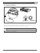
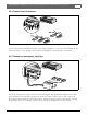
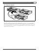
4 External settings and connections (system pre-amplifier)
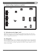
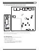
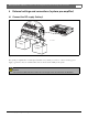
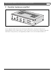
4.1 Connect the DC supply (battery)
Figure 4.1
The system pre-amplifier has a 24 Vdc input (terminal screw), which you can use to connect a back up power
supply, e.g. batteries. You can earth the unit to increase the electrical stability of the system.
Caution
The connection cable must have an in-line fuse. Use the type of fuse as mentioned in the illustration.
External settings and connections
115V-
2
3
0V
-
In
+2
4V-
+24V-
Rat
e
di
n
pu
t
Po
we
r
:
50
VA
T
1
.0
AL
25
0
V
A
p
par
at
u
s
d
el
i
ve
r
ed
c
o
nn
e
ct
e
d for230V
-
T
hi
s
app
a
rat
u
s
must
bee
a
rthe
d
W
arnin
g
Master
O
ut
1-
4
3
5
T
r
i
g
g
e
r1
T
e
l/EMG
0
Ou
t
Call In
Call Acti
v
e
Zone 6
Zone 5
Zon
e1
CD
L
R
T
rigg
er2
PCAu
dioIn
1
.
A
udio+
2.0V
3.Au
dio-
4.24Vd.c.
5.A
ll
call
6.
D
ata-
7
.
D
ata+
8
.
C
hs.G
N
D
L
B
B
19
2
5
/
0
0
8
90
0
1
92
50
0
0
5
1
15
/23
0
V~,50
/
6
0
Hz
No.
R
S23
2
/
Line
/Line
Aux
3
5
4
1
2
3
7
6
8
5
4
1
2
2
1
+
-
GND
3
1
2
+
-
G
ND
3
Zone 2
Zone 3
Zone 4
DC
O
u
t
DC I
n
100V
100V 0
0
100V
0
100V
0
1
00
V
100V
0
0
10
0
V
100V 0
0
00V
0
100V
0
100V
0
100V
0
100V
0
+24V-
+24V-
115V- 23
Thisapparatus must be earthed
Warning
12 VDC
12 VDC
-
+
-
+
F
F=1.5A
Apparatus delivered
connectedfor230V-
In
Call In
Call Active
6
Zone 3
Zone 4
DC Out
DC In
0V
0