INSTALLATION/OPERATION TXB-B Translator Board C2431M-I (4/07)
Contents Important Safety Instructions. . . . . . . . . . . . . . . . . . . . . . . . . . . . . . . . . . . . . . . . . . . . . . . . . . . . . . . . . . . . . 3 Regulatory Notices . . . . . . . . . . . . . . . . . . . . . . . . . . . . . . . . . . . . . . . . . . . . . . . . . . . . . . . . . . . . . . . . . . . . . 4 Description . . . . . . . . . . . . . . . . . . . . . . . . . . . . . . . . . . . . . . . . . . . . . . . . . . . . . . . . . . . . . . . . . . . . . . . . . . . 5 Parts List . . . . . . . .
Important Safety Instructions 1. Read these instructions. 2. Keep these instructions. 3. Heed all warnings. 4. Follow all instructions. 5. Only use attachments/accessories specified by the manufacturer. 6. Installation should be done only by qualified personnel and conform to all local codes. Only use replacement parts recommended by Pelco. The product and/or manual may bear the following marks: This symbol indicates that dangerous voltage constituting a risk of electric shock is present within this unit.
Regulatory Notices This device complies with Part 15 of the FCC Rules. Operation is subject to the following two conditions: (1) this device may not cause harmful interference, and (2) this device must accept any interference received, including interference that may cause undesired operation. RADIO AND TELEVISION INTERFERENCE This equipment has been tested and found to comply with the limits of a Class B digital device, pursuant to Part 15 of the FCC Rules.
Description The TXB-B translator board allows Bosch (Philips, Burle) controllers to communicate with Pelco’s Esprit®, ExSite™, and Spectra® systems. Once installed the Spectra dome, Spectra Mini dome, ExSite, or Esprit system receives Manchester code commands from the Bosch (Philips, Burle) controller and converts the commands into Pelco’s D protocol.
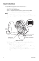
Esprit Installation To install the TXB-B translator board in an Esprit system (refer to Figure 1): 1. Turn off power to the Esprit system. 2. Remove the left cover from the pan and tilt. 3. Remove the shorting plug from the 16-pin connector on the Esprit system’s circuit board. 4. Remove the nut and washer from the standoff on the Esprit system’s circuit board. NOTES: • Discard the 6-32 and 4-40 screws and their lock washers; they are not used in the Esprit system. • Save the 16-pin shorting plug.
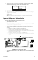
16-PIN CONNECTOR J1 RESET FOR LOOPING (UNTERMINATED) OPERATION TXB-B ADDRESS SWITCH J1 UNTERMINATED FRONT J1 TERMINATED BACK Figure 2. TXB-B Termination and DIP Switch 6. Set the address of the TXB-B (refer to Table C, Table D, and Table E in the Appendix beginning on page 25). 7. Install the TXB-B on the Esprit circuit board (refer to Figure 3): a. Insert the 16-pin connector on the bottom of the TXB-B into the mating 16-pin connector on the Esprit circuit board. b.
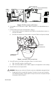
NOT SEALED CORRECT INCORRECT GAP Figure 4. Installing the Esprit Cover b. Apply pressure and push the top of the cover down to align the screw holes (refer to Figure 5). c. Insert the Phillips screw and tighten. Tighten until the screw will not turn. TOP GASKET FRONT RAIN GUARD Figure 5. Installing the Esprit Cover 10. Remove the pan and tilt from the base of the Esprit system.
11. Check the control wiring inside the base of the unit. Refer to the Esprit documentation and the documentation supplied with your controller to make sure the wiring is correct. Bosch (Philips, Burle) Controller Esprit Wire Harness - RX- (Green) + RX+ (Red) 12. Reattach the pan and tilt onto the base of the unit. 13. Apply power to the system. The following message appears on the monitor as soon as the Esprit configuration cycle is completed: TXB-B Rev x.xx yy NOTE: x.
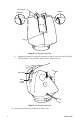
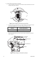
6. Install the TXB-B translator board into the back box: a. Open the hinged door to the back box. Push the tab lock towards the back box wall of the unit and open the door (refer to Figure 7). b. Check the wiring to the controller. Refer to the Spectra III/Spectra IV documentation and the documentation supplied with your controller to make sure the wiring is correct. Figure 7. Spectra III/Spectra IV Back Box Interconnect Door Bosch (Philips, Burle) Controller c.
NOTES: • • Discard the 4-40 screw and its lock washer; they are not used in the Spectra III/ Spectra IV system. Save the 16-pin shorting plug. Otherwise, the Spectra III/Spectra IV cannot be converted back to a Pelco-controlled system. d. Insert the TXB-B board into the 16-pin connector located on the back box circuit board. Secure the translator board to the standoff on the circuit board using the supplied 6-32 screw and lock washer. e. Close the interconnect door. Snap the tab lock into place. 7.
8. Install the dome drive. Line up the blue (A) and red (B) tabs with the blue (A) and red (B) labels. When pushing the tabs in, insert one side, then the other. Continue pushing on the ends of the tabs until both tabs click into place. Refer to Figure 11. NOTE: Refer to the installation manual supplied with the Spectra III/Spectra IV dome for instructions on installing the back box, dome drive, and lower dome. Figure 11. Spectra III/Spectra IV Dome Drive Installation 9. Install the lower dome. 10.
Spectra Mini Dome Installation To install the TXB-B translator board in a Spectra Mini dome: NOTE: Installing a TXB-B into a mini dome increases unit height. In surface mount installations, you must cut a hole in the surface to accommodate the TXB-B cover. For an installation template and more information, refer to the Spectra Mini Dome Installation manual. 1. Turn off power to the dome system. 2.
5. Set the J1 jumper on the TXB-B to the proper termination setting (refer to Figure 13). Note the following: • • • • • By default, the J1 jumper is installed in the terminated position. All TXB-Bs in a daisy chain, except the last unit, must be unterminated. The total wire distance from the Bosch (Philips, Burle) controller to the last TXB-B in a daisy chain must be less than 4,000 ft (1,219 m). A maximum of 10 receivers can be installed on a single daisy chain.
REMOVE SHORTING PLUG Figure 14. Removing the Mini Dome Cover and Shorting Plug c. Insert the TXB-B translator board into the 16-pin connector on the Spectra Mini dome’s circuit board. d. Install the translator board cover that is supplied with the Spectra Mini dome. Figure 15.
8. Check the wiring to the controller. Refer to the Spectra Mini dome documentation and the documentation supplied with your controller to make sure the wiring is correct. Bosch (Philips, Burle) Controller Spectra Mini Dome RJ45-10 Connector - Pin 4 (RX-) + Pin 3 (RX+) 9. Refer to the installation manual for the Spectra Mini dome to complete the installation. 10. Apply power to the system.
ExSite Installation To install the TXB-B translator board in an ExSite unit: WARNING: To reduce the risk of ignition of hazardous atmospheres, disconnect the equipment from the supply circuit before opening. 1. Turn off the power to the ExSite. WARNING: Total weight of the pan and tilt component is 55 lb (25 kg). Use caution when lifting and assembling the pan and tilt component on the power module. It is recommended that nonslip gloves be worn during installation or removal. 2.
16-PIN CONNECTOR J1 RESET FOR LOOPING (UNTERMINATED) OPERATION TXB-B ADDRESS SWITCH J1 UNTERMINATED FRONT J1 TERMINATED BACK Figure 18. TXB-B Termination and DIP Switch 4. Set the address of the TXB-B (refer to Table C, Table D, and Table E in the Appendix begining on page 26). 5. Install the TXB-B board on the power module (refer to Figure 19): a. Remove the shorting plug from the 16-pin connector located on the ExSite’s circuit board. NOTES: • • b.
6. Check the wiring to the controller. Refer to the ExSite documentation and the documentation supplied with your controller to make sure the wiring is correct. Bosch (Philips, Burle) Controller ExSite Wire Harness + RX+ (Red) - RX- (Green) 7. Set the DIP switches on the ExSite system (refer to Figure 19 for switch location): a. SW3: Verify that all SW3 switches on the ExSite power module are set to the OFF position. b.
Operation Use one of the following commands to access the on-screen, programmable camera menus with the Philips (Burle) controller: ON 45 Enter or SET 95 Enter CONTROLLER COMMANDS AND SYSTEM RESPONSE The following tables show how the TXB-B board and the Pelco unit respond to the Bosch (Philips, Burle) keyboard commands. Refer to the documentation supplied with the Bosch (Philips, Burle) controller and the Pelco system for operating instructions. Table A.
Table B. Special Functions (Continued) ON 17 Enter Set fixed speed 46°/sec OFF 17 Enter Acknowledge alarm ON 18 Enter Set fixed speed 60.
Table B.
TXB-B ZONE PROGRAMMING PROCEDURE A zone is a pan area, defined by a left and right limit, on the 360-degree pan plane. To program a zone with a Bosch (Philips, Burle) controller, refer to the manual supplied with the controller and perform the following: Step Procedure 1. Enter zone programming. Issue the enable zone scan command (ON 60 Enter) to display the zone labels. 2. Set left zone limit. Position the Pelco unit at the left limit of the zone.
Troubleshooting Symptom Possible Cause Suggested Remedy Video does not appear on screen. Power is not connected to the Pelco unit. Check the power connector. Video cable is not connected to the Pelco unit. Check the video connector. Translator board is not inserted properly. Reinstall the translator board. Make sure the pins on the board are inserted correctly.
Appendix Perform the following steps to find and set the addresses for the TXB-B board and the Pelco unit. 1. Refer to Table C on page 26 to find the TXB-B address (block number). Select the block range that contains the receiver address. The block number for the block range is the address for the TXB-B translator board. Example: To find the TXB-B address when the receiver address is 131: a. Find the block range for 131 in Table C. This value is between 129 (low) and 255 (high). b.
Table C.
Table D.
Table D.
Table D.
Table D.
Table D.
Table D.
Table D.
Table D.
Table D.
Table D.
Table D.
Table D.
Table D.
Table D.
Table D.
Table D.
Table E.
Table E.
Table E.
Table E.
PRODUCT WARRANTY AND RETURN INFORMATION WARRANTY Pelco will repair or replace, without charge, any merchandise proved defective in material or workmanship for a period of one year after the date of shipment. Exceptions to this warranty are as noted below: • Five years on fiber optic products and TW3000 Series unshielded twisted pair transmission products. • Three years on Spectra® IV products. • Three years on Genex® Series products (multiplexers, server, and keyboard).
Worldwide Headquarters 3500 Pelco Way Clovis, California 93612 USA USA & Canada Tel: 800/289-9100 Fax: 800/289-9150 International Tel: 1-559/292-1981 Fax: 1-559/348-1120 www.pelco.