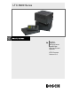
LTC 8900 Series User Manual EN Allegiant® Microprocessorbased Video Switcher/Control Systems CPU Firmware Version 10.
LTC 8900 | User Manual | Table of Contents EN | 2 Table of Contents 1 2 3 3.1 3.2 3.3 3.4 3.5 3.6 3.7 3.8 4 4.1 5 5.1 5.2 5.3 5.4 5.5 5.6 5.7 6 6.1 7 7.1 8 9 10 INTRODUCTION . . . . . . . . . . . . . . . . . . . . . . . . . . . . . . . . . . . . . . . . . . . . . . . . . . . . . . . . . . . . . . . . . .3 THIS MANUAL . . . . . . . . . . . . . . . . . . . . . . . . . . . . . . . . . . . . . . . . . . . . . . . . . . . . . . . . . . . . . . . . . . . .3 VIDEO MONITOR DISPLAY . . . . . . . . . . . . . . . .
EN | 3 LTC 8900 | User Manual | Introduction 1 INTRODUCTION The LTC 8900 Allegiant Series is a video switching/controller system designed to handle up to 4096 cameras and 512 monitors, in a full crosspoint configuration. Although the LTC 8900 Series is a very sophisticated product, it has been designed with the novice user in mind. The system can be operated using its default configuration, or it can be customized using the PC-based software package.
EN | 4 LTC 8900 | User Manual | Video Monitor Display Typically, various system parameters are configured by the installer via the PC-based configuration software package at installation. These programmable options include entry of camera titles, user information, alarm functions, lockout tables, sequences, time events, and other operational functions. These programmable features have a great effect on system operation and operator privileges.
EN | 5 LTC 8900 | User Manual | Video Monitor Display 3.2 Monitor Title/System Status Display The monitor title/system status display area is a 12-column display to the right of the camera number. It is unique on each monitor, and has different uses, some of which may be user-selected via keyboard.
EN | 6 LTC 8900 | User Manual | Video Monitor Display 3.2.6 Location 7 - Remote Lock Indication This location will display characters RL to indicate that control over the movements of the camera being viewed have been locked by a user. Control over this camera is now possible only by the user who locked the camera, or has higher priority. If the camera is not locked, the icon is not displayed. If a user error has occurred, this location will temporarily hold part of the error number. 3.2.
EN | 7 LTC 8900 | User Manual | Video Monitor Display 3.6 Camera Number The left-most display on the top line shows the systemgenerated camera number, and is always displayed. This unique number identifies this camera when using the keyboard for video call-ups. In base systems, this number is the same as the numbered BNC connector that the camera is plugged into on the rear of the bay (physical camera number).
EN | 8 LTC 8900 | User Manual | Keyboard Operation 4.1 User Priority Access Table The following table shows system function access for the 64 levels of users.
LTC 8900 | User Manual | Keyboard Operation Enter your assigned user number via the numeric keypad and press ENTER. When prompted, enter the password. Invalid passwords cause the keyboard to revert to its initial state. Once the login is successful, the keyboard will show camera and monitor numbers in its display. Upon logging in, the monitor controlled by the keyboard may automatically switch to a pre-assigned camera number.
LTC 8900 | User Manual | Keyboard Operation With LTC 8555 Series keyboards, press Monitor, Lock, then ON to lock a monitor, or OFF to unlock the monitor. If the monitor to be unlocked is not the one currently being controlled by the keyboard, enter the monitor number (but do not press ENTER) after pressing Monitor. If the Status option is enabled, the section of the onscreen overlay between the camera number and the time shows ML, indicating the monitor is locked.
EN | 11 LTC 8900 | User Manual | Keyboard Operation DITHER is a legacy Allegiant receiver/driver feature designed to extend the life of tube-based low-light level cameras. Its function was to prevent bright lights in the scene from burning a spot on the camera imager. When this feature is active, and the pan/tilt is not moved for a period of about 2 minutes, the receiver/driver automatically pans right for approximately 0.5 seconds.
LTC 8900 | User Manual | Keyboard Operation 5.6 Sequence Control 5.6.1 Load/Clear a Sequence To load a previously programmed sequence to run on your monitor, press Load Sequence [Seq], enter the desired sequence number (1 to 256), then press ENTER. Note that loading a sequence does not automatically start the sequence. Since sequences may be programmed to use more than one monitor, all required monitors must be available.
LTC 8900 | User Manual | Keyboard Operation 5.7 Sequence Programming 5.7.1 Programming a Simple Camera Sequence The Allegiant system has very powerful sequencing capabilities. Using a system keyboard, it is possible to enter sequences to run on a single or multiple monitors. As long as valid camera and monitor numbers are used, they can be entered into a sequence randomly.
EN | 14 LTC 8900 | User Manual | Keyboard User Functions To edit an existing sequence, press Program Sequence [Prog], enter the existing sequence number, then press ENTER. You can insert a line into a sequence by navigating down to the line where inserting a new line, and press Insert Step [ON]. A new line identical to the one you are on is added to the next step. To delete a step, navigate to the line to be deleted, and press Delete Current Step [OFF].
EN | 15 LTC 8900 | User Manual | Keyboard User Functions Fn# 1 2 3 4 5 6 7 8 9 10 11 12 13 14 15 16 17 18 19 20 21 22 23 24 25 26 27 28 29 30 31 32 33 34 35 36 37 38 39 40 41 42 43 44 45 46 47 99 Joystick Up/Down n/a n/a n/a Up/Down Brightness Time/Date ON/OFF Set Set Set n/a Select n/a Select n/a n/a Select Set Select Select Select Select Select n/a Up/Down Brightness Time/Date Keyboard Login Console Login Default Parameters Controller Parameters Console Parameters Alarm Parameters n/a Select Camera No.
LTC 8900 | User Manual | Keyboard User Functions 6.1.2 User Function 1 Local Keyboard Test User Function 1 can be used as a local test to ensure that all the keyboard LEDs and switches are working. This function automatically calibrates the center position of the analog joystick on LTC 8555 keyboards. Upon entering this test, the keyboard will beep and all LEDs will illuminate for about two seconds. Note if there are any LED failures.
LTC 8900 | User Manual | Keyboard User Functions 6.1.7 User Function 6 Select Monitor Display Option User Function 6 allows removal of the time and date (the left-hand side of the display), or the entire display from the individual monitor. If using the LTC 8555 Series keyboard, move the joystick down to blank the time and date from the screen. This is sometimes desirable when a VCR, with its own time and date, is being used. Move the joystick up to add the time and date back.
LTC 8900 | User Manual | Keyboard User Functions 6.1.13 User Function 12 Default All Monitor Overlays User Function 12 can be used by users with the priority level 1, to reset all monitor overlays to default characteristics (bottom center of screen), and full brightness. After entering the mode, press ENTER to reset all monitor overlays. If using the LTC 8555 Series keyboard, press USER to exit. 6.1.
LTC 8900 | User Manual | Keyboard User Functions 6.1.21 User Function 20 Select Printer Verbosity Priority level 1 users can use this function to select between print modes; Limited Printing and Full Printing. This selection determines the amount of information printed during alarm processing. Both modes print alarm activation and deactivation messages, but Full Printing goes into much more detail. Use the joystick to select the desired mode, then press ENTER.
LTC 8900 | User Manual | Keyboard User Functions Move the joystick to the left to blank the left-hand side of the display from the monitor and to the right to return it. Refer to User Function 5 or 25 to verify brightness level. Press ENTER to update all system monitors to the selected format. If using the LTC 8555 Series keyboard, press USER to exit. 6.1.28 User Function 27 Select Keyboard Login This function controls the system s keyboard login feature.
EN | 21 LTC 8900 | User Manual | Keyboard User Functions 6.1.35 User Function 34 Camera Indicator Priority 1 users can use this function to enable an onscreen indicator to identify a pan/tilt equipped camera. Move the joystick up/down to select DISP CAM CONTROL or NO CAM CONTL DISPL. Press ENTER to activate your selection. When enabled, cameras identified as controllable (via User Function 35 or the PC software package), show a in the middle of the first line of monitor text. 6.1.
EN | 22 LTC 8900 | User Manual | Keyboard User Functions In addition, this option changes the behavior of how the system determines which Trunk Line to use. When this option is not used, a new Trunk Line (if available) will be used for each camera selection. When this option is enabled, an operator’s monitor will use the same Trunk from the same bay as different cameras are selected, as long as no other operator is viewing the same Satellite camera.
EN | 23 LTC 8900 | User Manual | Maintenance Some minor disturbance of the video images may be visible for 1 or 2 seconds while the cameras are being adjusted. If no changes are noticed, check to make sure that you have compatible devices in your system. If using an LTC 8555 keyboard, press USER to exit the mode. User Function 45 CPU Temperature Status Use this function to view the condition of the CPU temperature. Once the function is entered, the condition is displayed on the monitor text display.
LTC 8900 | User Manual | LTC 8900 Character Set 8 LTC 8900 CHARACTER SET Bosch Security Systems | March 17, 2009 EN | 24
LTC 8900 | User Manual | Character Set Bosch Security Systems | March 17, 2009 EN | 25
LTC 8900 | User Manual | Character Set Bosch Security Systems | March 17, 2009 EN | 26
LTC 8900 | User Manual | LTC 8900 Character Set Bosch Security Systems | March 17, 2009 EN | 27
LTC 8900 | User Manual | LTC 8900 Character Set Bosch Security Systems | March 17, 2009 EN | 28
LTC 8900 | User Manual | LTC 8900 Character Set Bosch Security Systems | March 17, 2009 EN | 29
LTC 8900 | User Manual | LTC 8900 Character Set Bosch Security Systems | March 17, 2009 EN | 30
EN | 31 LTC 8900 | User Manual | Error Messages 9 ERROR MESSAGES Error Error Description Error 01 The camera number entered from the Invalid camera request keyboard does not exist. If using the LTC 8059/00 MCS or the LTC 8850/00 GUI software, ensure that the number exists in the Camera Identification table. Download the table to be sure. Description Error 20 Acknowledge denied ACKNOWLEDGE has been pressed by a user without authority to acknowledge alarms.
EN | 32 LTC 8900 | User Manual | Error Messages Error Description Error Description Error 55 SEQUENCE priority The switcher sequence being requested or cleared requires monitors that are in use by a user of equal or higher priority. Contact a user with higher priority, or have the system administrator clear the monitors in question. Error 80 Trunk not available An attempt was made to access a remote camera connected to a satellite system, but no unused trunk lines are currently available.
LTC 8900 | User Manual | Glossary of Terms 10 EN | 33 GLOSSARY OF TERMS Term Definition AUXILIARY An auxiliary is an additional function of the remote receiver/driver, which permits on/off control of outputs available to the user. In the Allegiant system, four relay outputs are available, which can be configured for contact closures, 24VAC output, or LINE voltage output. Additionally, they can be set to activate either momentarily, or in a latching mode.
LTC 8900 | User Manual | Bosch Security Systems | March 17, 2009 EN | 34
LTC 8900 | User Manual | Bosch Security Systems | March 17, 2009 EN | 35
Americas Bosch Security Systems, Inc. 850 Greenfield Road Lancaster, Pennsylvania 17601 USA Telephone +1 888-289-0096 Fax +1 585-223-9180 Email: security.sales@us.bosch.com www.boschsecurity.us Europe, Middle East, Africa: Bosch Security Systems B.V. P.O. Box 80002 5600 JB Eindhoven, The Netherlands Phone: + 31 40 2577 284 Fax: +31 40 2577 330 emea.securitysystems@bosch.com www.boschsecurity.com 2009 Bosch Security Systems, Inc.