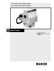
LTC 9418 & LTC 9420 Series LTC 9440 & LTC 9441 Series Instruction Manual EN Medium & Heavy Duty Pan Tilts
IMPORTANT SAFEGUARDS 12. Power Lines - An outdoor system should not be located in the vicinity of overhead power lines or other electric light or power circuits or where it can fall into such power lines or circuits. When installing an outdoor system, extreme care should be taken to keep from touching such power lines or circuits as contact with them might be fatal. U.S.A. models only - refer to the National Electrical Code Article 820 regarding installation of CATV systems. 13.
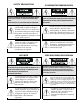
SAFETY PRECAUTIONS SICHERHEITSVORKEHRUNGEN CAUTION: TO REDUCE THE RISK OF ELECTRICAL SHOCK VORSICHT: UM EINEN ELEKTRISCHEN DO NOT OPEN COVERS. NO USER SERVICEABLE PARTS SCHLAG ZU VERMEIDEN, ABDECKUNG NICHT ENTFERNEN. INSIDE. WARTUNGEN ALLER ART QUALIFIZIERTEM PERSONAL REFER SERVICING TO QUALIFIED SERVICE PERSONNEL. ÜBERLASSEN.
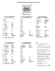
CONTENTS 1 2 3 3.1 3.2 3.3 3.4 3.5 3.6 3.7 3.8 4 4.1 4.2 4.3 4.4 4.5 4.6 5 6 7 Unpacking . . . . . . . . . . . . . . . . . . . . . . . . . . . . . . . . . . . . .4 Service . . . . . . . . . . . . . . . . . . . . . . . . . . . . . . . . . . . . . . . .4 INSTALLATION . . . . . . . . . . . . . . . . . . . . . . . . . . . . . . . . .5 Model Designation . . . . . . . . . . . . . . . . . . . . . . . . . . . . . . .5 Recommended Mounting Equipment . . . . . . . . . . . . . . . . . . .5 Wall Mounting . . . . . . .
3 INSTALLATION CAUTION: DO NOT EXCEED 30 VAC INPUT ON 24 VAC MODELS. OPERATION ABOVE 30 VAC VIOLATES LOW VOLTAGE OPERATION (CLASS 2 SPECIFICATIONS). NORMAL OPERATION IS 24 VAC. CUL APPROVED 24 VAC MODELS. THIS INSTALLATION SHOULD BE MADE BY A QUALIFIED SERVICE PERSON AND CONFORM TO ALL LOCAL CODES. CAUTION: CONNECT TO CLASS 2 POWER SUPPLY ONLY. TOTAL CURRENT THROUGH ELECTRICAL CONNECTOR IS 4 A MAXIMUM. PAN/TILT CURRENT IS 1 A MAXIMUM. ALLOWABLE CAMERA/HOUSING IS 3 A MAXIMUM.
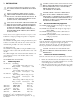
3.5 Electrical Connections 1. Cable must be wired according to Connector Assembly (Section 3.7) and Recommended Maximum Cable Lengths (Table 1). 2. Use separate shielded cables for camera power, enclosure power, and pan/tilt control. If required, combining lens control wiring and video coax within a common cable is acceptable. The use of a common multiconductor cable to combine all functions is not recommended. 3. Use color coded conductors to aid wiring and future identification. 4.
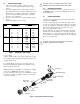
WIRE DESIGNATION AND PIN CONNECTIONS Figure 2: Pin Outs 345° Non-Pre-Position Models5,6 Feed -thru Wiring Pin 1: 2: 3: 4: 5: 6: 7: 8: 9: 10: 11: 12: 13: 14: 15: 16: 17: 18: 19: 20: 21: 22: 23: 24: Number NC1 NC1 NC1 NC1 Lens Common Zoom Focus Unused Unused Accessory Accessory Accessory NC1 NC1 NC1 Pan Left NC1 Pan Right P/T Common Tilt Up Tilt Down Ground Camera AC-Line Camera AC-Neutral Color Green2 Blue2 Violet2 Brown2 Black2 White2,3 Red2,3 Yellow2,3 White Violet Blue Brown White/Yellow Green/Yellow
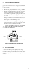
3.8 Pan Stops (345° Models) Locate the three (3) limit stops on the base of the unit. The red limit stop is the Fixed Stop. It is not adjustable and should not be removed. The remaining two (2) stops are called Pan Stops. These are positioned on each side of the pan switch lever. The two (2) pan stops are adjustable and secured with a set screw. The screws can be accessed through the hole in the end of each stop. Use a 3/32-inch Allen wrench (supplied) to loosen and tighten the set screw. See Figure 3. 4.
4.5 Tilt Stop Adjustment (All Models) After the unit is installed and all wire connections are made, apply proper power to the control unit. Refer to Figure 5, and adjust the tilt stops as follows: 1. 2. 3. 4. With the front of the pan/tilt facing you, remove the left hub cap. The tilt stop adjustment screws are now exposed. Using the control unit, tilt the bracket up to the desired position and stop the unit. Use the 3/32-inch Allen wrench to loosen the Tilt Up stop.
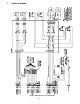
5 WIRING DIAGRAMS Figure 6: Wiring Diagram - 0º to 345º Models 10
Video Figure 7: Wiring Diagram - 360º Models 11
Video Control Figure 8 - 360º Models with Pre-Position 12
6 RECOMMENDED APPLICATIONS 360° Models Only Feed-thru 24 Volt Models USE ONLY 24 VOLT CAMERAS/HOUSINGS WITH 360° MODEL PAN/TILTS. TO MAINTAIN CUL AND TUV APPROVAL, USE ONLY 24 VOLT CAMERAS/HOUSINGS. THE MAXIMUM POWER FOR HEATER/BLOWER COMBINATIONS IS 75 WATTS TO PREVENT OVERLOADING THE SLIP RING. THIS LOAD MUST BE POWERED BY PIN 10, (WHITE FEED-THRU) AND PIN 11 (RED FEED-THRU). SEE FIGURE 2.
This page intentionally left blank 14
This page intentionally left blank 15
Bosch Security Systems, Inc. 850 Greenfield Road Lancaster, PA 17601 EE.UU. Tel: 800-326-3270 Fax: 717-735-6560 www.boschsecuritysystems.com Robert Bosch GmbH Geschäftsbereich Postfach 10 60 50 70049 Stuttgart Telefax (0711) 811-1234 @ 2003 Bosch Security Systems GmbH 100 0083 001 BOS 08/03 Data subject to change without notice. Bosch Security Systems B.V. P.O.