
Operation Manual


EN
|
12
Bosch Security Systems | 18 August 2005
LTC 8016/90 | Instruction Manual | Installation
4.5 Video Connections to
the Controller Unit
Video connections from the Interface Unit vary based
on the type of video connections available on the
controller, and the distance between the controller
and the Interface Unit. Review the options in the
table below to determine which best suits your
configuration, then follow the appropriate section
below:
Video output signals from the Interface Unit are
expecting to see a standard 75Ω termination. Unless a
video input will be used to loop out to another device,
make sure that the video inputs on the control unit are
properly set to provide 75Ω video termination. For
details on setting the video terminations of your
controller device, refer to the device’s installation
instructions.
The video connections from the Interface Unit MUST
be kept in consecutive order, and the group must
always end at an exact multiple of 16. For example,
the lowest camera group range is from 1 to 16. The
next group range is from 17 to 32, and so on, up to
the last group, that corresponds to the camera range
of 9985 to 9999. Always make video connections to
the controller following these guidelines.
Certain controller units support video looping
inputs. Do not connect a camera to the
looping output of a video channel on the
control unit that is already being used by the
Interface Unit. Smeared or double video
images will result. Alternate video
connections available on video control
systems should only be used for looping
video signals out to some other external
control system device or monitor.
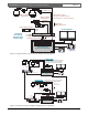
4.5.1 Video Connections to Products Supporting
Ribbon Cable Interface
Video connections from the Interface Unit to Allegiant
models LTC 8200, LTC 8300, LTC 8600, LTC 8800,
LTC 8900, and the DESA
XL
Series Digital Video
Recorders use the supplied video ribbon cable. Noting
the video ribbon cable connector’s orientation and
alignment tab, connect one end of the supplied
16-channel ribbon cable to the back of the Interface
Unit. Place the other end into the connector on the
rear panel of the controller unit that corresponds to the
physical camera number range previously determined
by the Group ID switch settings (described above). For
example, if the Group ID switches have been set to
003, the video ribbon cable should be installed into
the Allegiant connector corresponding
to video inputs 33 to 48.
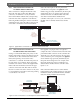
LTC 8016 Interface Unit
2m (6ft) Supplied
Video Ribbon Cable
LTC8200
KEYBOARD
CONSOLE
MONITOR OUTPUTS
CAMERA INPUTS
ALARM 1-8
BIPHASE OUT
BIPHASE OUT
RELAY OUT
1
9
2
10
3
11
4
12
5
13
14
6
7
15
8
16
5
4
1
2
3
. . . . . . . . . . . . . . . . .
. . . . . . . . . . . . . . . . .
ALARM 9-16
BIPHASE OUT
PC
INPUTS
15
16
13
14
11
12
9
10
8
6
5
3
4
2
LOOPING VIDEO 1-16
. . . . . . . . . . . . . . . . .
. . . . . . . . . . . . . . . . .
7
1
RS-232
RS-485 IN
RS-485 OUT
DATA
ETHERNET
10/100 BaseT
ACTLINK
CODE
BIPHASE IN
GROUP ID
0
2
6
4
8
0
2
6
4
8
0
2
6
4
8
LTC 8200 Allegiant Series Switcher
Video Looping
Ribbon Connector
Figure 3 Interface Unit Video Connections to a Typical Allegiant System
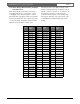
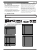
Controller Type Configuration
Method
Max Separation
Distance
Allegiant Series LTC 8200,
LTC 8300, LTC 8600,
LTC 8800, and LTC 8900,
DESA
XL
DVR Series
Use 16-channel
video ribbon
cable, supplied
with the
LTC 8016
2 m (6 ft)
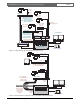
Any controller system
using BNC connectors
Use the optional
LTC 8508/01
16-channel
ribbon-to-BNC
video cable
1 m (3 ft)
Any controller system
using BNC connectors
Use the
16-channel
video ribbon
cable supplied
with the
LTC 8016, to
the optional
LTC 8807/00
panel, then
BNC to user-
supplied video
link
Distance is
limited only by
the type of user-
supplied video
transmission link