
Operation Manual


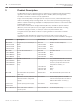


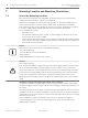


Table Of Contents
- Title Page
- Table of Contents
- Safety
- Unpacking
- Product Description
- Overview of Installation Steps
- Configuration Programming in the Shipping Box
- Configuration Programming on a Temporary Table-top Stand
- Mounting Location and Mounting Orientation
- Overview of Mounting Options
- Install the Camera
- Make Connections - Power and Control
- Cant the Camera
- Typical System Configurations
- Configuration
- Configuration via IP, Basic Mode
- Configuration via IP, Advanced Mode
- Advanced Mode: General
- Identification
- Password
- Date/Time
- Display Stamping
- Advanced Mode: Web Interface
- Appearance
- LIVE Functions
- Logging
- Advanced Mode: Camera
- Installer Menu
- Encoder Profile
- Encoder Streams
- Privacy Masks
- Picture Settings
- Lens Settings
- PTZ Settings
- Illumination/Wiper
- Scenes and Tours
- Sectors
- Miscellaneous
- Audio
- Pixel Counter
- Advanced Mode: Recording
- Storage Management
- Recording Profiles
- Maximum Retention Time
- Recording Scheduler
- Recording Status
- Advanced Mode: Alarm
- Alarm Connections
- VCA
- Virtual Masks
- Audio Alarm
- Alarm E-Mail
- Alarm Task Editor
- Alarm Rules
- Advanced Mode: Interfaces
- Alarm Inputs
- Alarm Outputs
- Advanced Mode: Network
- Network Access
- DynDNS
- Advanced
- Network Management
- Multicast
- Image Posting
- Accounts
- IPv4 Filter
- Encryption
- Advanced Mode: Service
- Maintenance
- Licenses
- Diagnostics
- System Overview
- Operation
- Troubleshooting
- Maintenance
- Decommissioning
- Technical data
- Keyboard Commands By Number
- Back Page

Figure 7.1: Top view of canted MIC7000 illustrating distance of pan clearance
The figure below illustrates the tilt range of the camera in upright orientation.
55° 55°
90° 90°
AutoPivot
Figure 7.2: MIC7000 Tilt Range: 145° each direction; 290° if AutoPivot enabled
20
en | Mounting Location and Mounting Orientation
MIC IP starlight 7000 HD, MIC IP
dynamic 7000 HD
2014.05 | 1.0 | F.01U.291.520 Operation Manual Bosch Security Systems, Inc.