
User Manual

MIC Series IP Power Supply Installation | en 15
Bosch Security Systems, Inc. User Manual F.01U.265.804 | 1.6 | 2012.08
3.4 MIC Power Supply Units (PSUs) for IR MIC Cameras
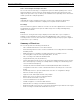
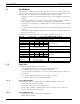
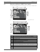
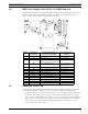
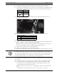
The figure below displays the layout of the PCB in the MIC PSUs for IR cameras, with call-out
numbers to the side of or below the connection/terminal ID or the terminal, and ’on’ the
fuses. The table below the figure identifies the connections.
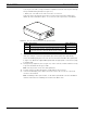
Figure 3.4 Layout of PCB in enclosure of PSU for MIC IR cameras
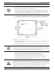
3.5 Earth Link on the PCB
The printed circuit board (PCB) of each MIC PSU (IR and non-IR) has one Earth Link option,
near terminal block HD1, to allow the PSU to be set up for different earthing schemes:
– If there is a separate connection between video screen and earth, the Earth Link should
be broken. This usually occurs on copper-connected systems where all of the copper
video coaxes are taken back to the control room to be connected to a central earth point.
– If fiber optics or other indirect connections are used to get data and video to and from
the control room, then the Earth Link should be left intact, as long as it is the only
camera-end earth reference point.
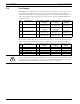
Number Connection /
Terminal ID
Description/Function of
Connection / Terminal
Type of Connection /
Terminal
1 HD1 AC Power input Screw terminal
2 HD2 4-input alarm Screw terminal
3 HD3 Shielded composite cable
(analog connections to camera)
Screw terminal
4 HD4 USB to RS-485 converter Screw terminal or
Molex connector
4 HD5 RS-485 control
5 HD6 [Optional] Auxiliary, IR lamps Screw terminal
6 HD7 Washer drive Screw terminal
7 CN1 (Video Out) Coax connection BNC socket
8 Earth Link Earth Link --
9 FS2 Fuse 2 - Primary protection --
10 FS4 Fuse 4 - washer drive --
11 FS3 Fuse 3 - IR lamps --
12 FS1 Fuse 1 - MIC camera protection --
13 FS5 Fuse 5 - MIC camera protection --