
User Manual
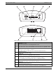

MIC Series IP Power Supply Installation | en 21
Bosch Security Systems, Inc. User Manual F.01U.265.804 | 1.6 | 2012.08
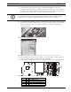
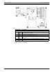
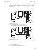
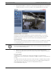
Figure 3.8 Encoder connections front (top half of graphic) and back (bottom half of graphic)
Number Description
1 VIDEO IN video input
BNC socket (75 ohm) for connecting the video source
2 SD CARD slot
(The release letter of the current firmware version has a list of compatible cards.)
3 POWER LED
lights up green when ready for operation
(See "LEDs" in the User Manual for more information about the LEDs.)
4 Factory reset button
to restore factory default settings
5 LINE IN/OUT
For audio connection (not applicable to MIC cameras)
6 Terminal Block
for alarm inputs, relay outputs, serial interface and power supply
(See "Terminal block" in the Appendix of the User Manual for details.)
7 Green LED
lights up when the unit is connected to the network
8 Orange LED
lights up during data transmission
9 ETH RJ45 socket
for connecting to an Ethernet LAN (local network), 10/100 MBit Base-T