
Installation Guide
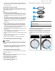
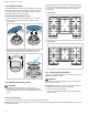
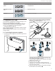
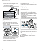
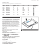
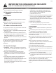
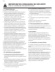
Table Of Contents
- Built-in gas hob
- en-us
- Table of contents
- 1 IMPORTANT SAFETY INSTRUCTIONS
- 1.1 Safety definitions
- 1.2 General information
- 1.3 General safety instructions
- 1.4 Appliance handling safety
- 1.5 Safety codes and standards
- 1.6 Electrical safety
- 1.7 Gas safety
- 1.8 Propane gas installation
- 1.9 Ventilation recommendations
- 1.10 High altitude installation
- 1.11 State of California Proposition 65 Warnings
- 2 Before you begin
- 3 Prepare installation space
- 4 Installation procedure
- 4.1 Preparing the cooktop
- 4.2 Installing the pressure regulator
- 4.3 Securing the cooktop to the countertop
- 4.4 Connection overview
- 4.5 Connecting the gas supply line
- 4.6 Connecting the electrical supply
- 4.7 Assembling the burner parts
- 4.8 OptiSim® feature
- 4.9 Installing the burner grates
- 4.10 Checking the installation
- 5 Conversion to LP gas
- 6 Customer Service
- fr-ca
- Table des matières
- 1 IMPORTANTES CONSIGNES DE SÉCURITÉ
- 1.1 Définitions des termes de sécurité
- 1.2 Indications générales
- 1.3 Consignes générales de sécurité
- 1.4 Manipulation sécuritaire des appareils
- 1.5 Codes et normes de sécurité
- 1.6 Sécurité électrique
- 1.7 Sécurité des gaz
- 1.8 Installation au gaz propane
- 1.9 Recommandations de ventilation
- 1.10 Installation à haute altitude
- 1.11 Mises en garde conformément à la proposition 65 de l'État de Californie
- 2 Avant de commencer
- 3 Préparation préalable au montage
- 4 Procédure d’installation
- 4.1 Préparation de la table de cuisson
- 4.2 Installation du régulateur de pression
- 4.3 Fixation de la table de cuisson au comptoir
- 4.4 Aperçu de la connexion
- 4.5 Raccordement de la conduite d’alimentation en gaz
- 4.6 Connexion de l'alimentation électrique
- 4.7 Assemblage des pièces du brûleur
- 4.8 OptiSim® fonctionnalité
- 4.9 Installation des grilles de brûleur
- 4.10 Inspecter l’installation
- 5 Conversion au gaz LP
- 6 Service à la clientèle
- es-mx
- Tabla de contenidos
- 1 INSTRUCCIONES DE SEGURIDAD IMPORTANTES
- 1.1 Definiciones de seguridad
- 1.2 Indicaciones generales
- 1.3 Instrucciones generales de seguridad
- 1.4 Seguridad de manejo del aparato
- 1.5 Códigos y normas de seguridad
- 1.6 Seguridad eléctrica
- 1.7 Seguridad de los aparatos de gas
- 1.8 Instalación con gas propano
- 1.9 Recomendaciones de ventilación
- 1.10 Instalación a gran altitud
- 1.11 Advertencias en virtud de la Proposición 65 del estado de California
- 2 Antes de empezar
- 3 Preparar el lugar de instalación
- 4 Procedimiento de instalación
- 4.1 Preparación de la placa de cocción
- 4.2 Instalar el regulador de presión
- 4.3 Asegurar la parrilla a la superficie de trabajo
- 4.4 Descripción general de la conexión
- 4.5 Conectar el conducto de suministro de gas
- 4.6 Conectar el suministro eléctrico
- 4.7 Colocar los componentes de los quemadores
- 4.8 Función OptiSim®
- 4.9 Instalar las rejillas de los quemadores
- 4.10 Comprobar la instalación
- 5 Conversión a gas LP
- 6 Servicio de atención al cliente

Conversion to LP gas en-us
13
Flame Image Measure
Completely or mostly
yellow
Verify that the regulator is set for the correct fuel. Retest af-
ter adjustment.
Yellow tips on outer
cone
Normal for LP gas
Soft blue Normal for natural gas
Conversion to LP gas
5 Conversion to LP gas
Conversion to LP gas
Your appliance is equipped for use with natural gas on de-
livery. It can be changed to LP gas supply.
The components required for conversion to LP Gas are
contained in the conversion kit included with this appli-
ance, or are available from Customer Service.
→
"Customer Service", Page15
Only a licensed specialist is authorized to switch the appli-
ance to another gas type.
Before carrying out the conversion, turn off the electricity
and gas supply.
5.1 Converting the pressure regulator
1. Locate the pressure regulator on the bottom right end of
the appliance.
2. Remove the hexagon shaped cap from the regulator.
Make sure not to dislodge the gasket on the cap or
the spring inside the regulator.
3. Grasp the plastic button stem firmly and pull it force-
fully from the metal cap .
The stem snaps snugly into an indent in the cap and
may require a strong pull to remove.
It may be helpful to gently “rock” the plastic stem while
pulling it from the metal cap.
4. Rotate the stem 180° .
a The button end of the stem is away from the cap.
a The letters “LP” on the stem are upside down when the
cap is set flat on its head.
5. Snap the stem back in place in this position inserting it
into the indent in the metal cap .