
Gas Conversion Installation
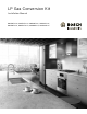


Table Of Contents
- LP Gas Conversion Kit
- Table of ContentsUse and care manual
- Safety DefinitionsSafety Definitions
- IMPORTANT SAFETY INSTRUCTIONS
- READ AND SAVE THESE INSTRUCTIONS
- 2. Shut-off valve must be a “T” handle gas cock.
- 3. Flexible gas connector must not be longer than 36 inches.
- CAUTION
- When connecting the unit to the propane gas, make certain the propane gas tank is equipped with its own high pressure regulator. In addition, a pressure regulator was supplied with the cooktop. This second regulator must be installed with the cooktop...
- The following must be met when testing supply piping system:
- a) The appliance and its individual shut-off valve must be disconnected from the gas supply piping system at test pressures in excess of 1/2 psig (3.5 kPa).
- b) The appliance must be isolated from the gas supply piping system by closing its individual manual shut-off valve during any pressure testing of the gas supply piping system at test pressures equal to or less than 1/ 2 psig (3.5 kPa).
- State of California Proposition 65 Warning:
- Tools and Parts Needed
- Checklist
- Step 1 - Convert the pressure regulator
- Note:
- 1. Remove the hexagon shaped cap from the regulator making sure not to dislodge the gasket on the cap or the spring inside the regulator.
- 2. Grasp the plastic button stem firmly and pull it forcefully from the metal cap. The stem snaps snugly into an indent in the cap and may require a strong pull to remove. (Hint: it may be helpful to gently “rock” the plastic stem while pulling i...
- 3. After removing the stem from the cap, rotate the stem 180° so the button end of the stem is away from the cap and the letters “LP” on the stem are upside down when the cap is set flat on its head. Snap the stem back in place in this position ...
- 4. Important: Attach the metallic sticker (included with this conversion kit) to the bottom of the appliance as shown, placing it near the appliance data plate (shows model number and information about the appliance). This sticker provides notice tha...
- Step 2 - Replace the orifices
- NGM5056UC
- NGM8056UC, NGM8046UC
- NGMP656UC
- NGMP056UC
- NGM5655UC, NGM8656UC, NGM8646UC
- 4. Insert each of the LP gas orifices provided with this kit into the socket (using the small piece of foam tape to assure a tight fit).
- Step 3 - Replace the burners, burner caps and grates
- Step 4 - Convert valves for LP gas
- 1. Turn all knobs to the “OFF” position.
- 2. Remove knobs.
- 3. Hollow Stem Valves (all burners except center valve of NGMP units): insert a long, thin flat blade screwdriver in the hollow stem of the valve. The adjustment screw is approximately 1 1/2" (39 mm) from the top of the stem.
- 4. Engage the tip of the screwdriver into the adjustment screw by slowly turning the screwdriver and feeling for the blade to engage the screw. Then turn the screw clockwise about 70 degrees (less than 1/4 turn) until it “bottoms out” (does not t...
- Check manifold gas pressure
- Final check
- Table des MatièresNotice d’utilisation
- Définitions de sécuritéDéfinitions de sécurité
- IMPORTANTES CONSIGNES DE SÉCURITÉ
- LIRE ET CONSERVER CES INSTRUCTIONS
- 2. Le robinet d'arrêt doit être robinet à gaz avec poignées en T.
- 3. Le connecteur à gaz souple ne doit pas dépasser 36 pouces.
- ATTENTION
- Lors du raccordement de l'appareil au gaz propane, assurez-vous que le réservoir de gaz est doté de son propre régulateur de pression élevée. De plus, un régulateur de pression a été livré avec la table de cuisson. Ce deuxième régulateur d...
- Veuillez respecter les exigences ci-dessous lors de la mise à l'essai de la canalisation du système d'alimentation en gaz :
- a) L'appareil et son propre robinet d'arrêt doivent être déconnectés de la canalisation du système d'alimentation en gaz aux pressions de test qui dépassent 1/2 PSIG (3,5 kPa).
- b) L'appareil doit être isolé de la canalisation du système d'alimentation en gaz en fermant son propre robinet d'arrêt manuel pour tout test à des pressions égales ou inférieur à 1/2 PSIG (3,5 kPa).
- Avertissement issue de la proposition 65 de l’État de la Californie :
- Outils et pièces nécessaires
- Liste de vérification
- Étape1 : Convertir le régulateur de pression
- Remarque :
- 1. Retirez le capuchon de forme hexagonale du régulateur. Assurez-vous de ne pas déloger le joint extérieur du capuchon ou le ressort à l'intérieur du régulateur.
- 2. Saisissez solidement la tige de plastique du bouton et tirez avec force pour le dégager du capuchon de métal. La tige s'enclenche et est bien serrée dans une rainure du capuchon et peut demander beaucoup de force pour la retirer. (Conseil : il ...
- 3. Après le dégagement de la tige du capuchon, tournez la tige sur 180 degrés de sorte que l'extrémité du bouton de la tige est à l'écart du capuchon et les lettres LP de la tige sont à l'envers lorsque le capuchon est à plat sur sa tête. E...
- 4. Important : Collez l'autocollant métallique (inclus dans cette trousse de conversion) au bas de l'électroménager, comme illustré, pour qu'il soit près de la plaque signalétique de l'appareil (indique le numéro de modèle et les renseignemen...
- Étape 2 : Remplacement des ports
- NGM5056UC
- NGM8056UC, NGM8046UC
- NGMP656UC
- NGMP056UC
- NGM5655UC, NGM8656UC, NGM8646UC
- 4. Insérer chaque port de gaz de PL (fourni dans cette trousse) dans la douille avec le petit morceau de ruban mousse pour assurer un ajustement serré.
- Étape 3 : Repositionnement des brûleurs, des chapeaux de brûleur et des grilles
- Étape 4 : Conversion des robinets pour le gaz de PL
- 1. Mettre tous les boutons à la position d'arrêt.
- 2. Retirer les boutons.
- 3. Robinets à tige creuse (tous les brûleurs sauf le robinet central des appareils à NGMP) : Insérer un long tournevis à lame plate et mince dans la tige creuse du robinet. La vis de réglage se trouve à environ 1½ po (39 mm) du haut de la tige.
- 4. Insérer l'extrémité du tournevis dans la vis de réglage et la tourner lentement pour sentir l'insertion de la lame dans la vis. Puis tourner la vis dans le sens horaire sur près de 70 degrés (moins de ¼ de tour) jusqu'à ce qu'il soit au fo...
- Vérification de la pression d'admission du gaz
- Dernière vérification
- ContenidoManual de instrucciones
- Definiciones de seguridadDefiniciones de seguridad
- INSTRUCCIONES DE SEGURIDAD IMPORTANTES
- LEA Y CONSERVE ESTAS INSTRUCCIONES
- 2. La llave de cierre tiene que ser una llave de gas en T.
- 3. El conector de gas flexible debe de tener una longitud no superior a 36 pulgadas.
- ATENCION
- Al conectar la unidad con el gas propano, asegurarse de que el tanque de gas propano esté equipado con su propio regulador de alta presión.Además, se suministra un regulador de presión con la placa de cocción.Este segundo regulador debe de insta...
- Al realizar pruebas en el sistema de tuberías de suministro, deben de cumplirse los siguientes requisitos:
- a) El electrodoméstico y su llave de cierre individual deberán estar desconectados del sistema de tuberías de suministro de gas cuando las presiones de las pruebas superen 1/2 psi (3.5 kPa).
- b) El electrodoméstico deberá aislarse del sistema de tuberías de suministro de gas cerrando su llave de cierre individual manual durante cualquier prueba de presión del sistema de tuberías de suministro de gas con presiones iguales o inferiores...
- Advertencia en virtud de la Proposición 65 del estado de California:
- Herramientas y piezas necesarias
- Lista de comprobación
- Paso 1 - Convertir el regulador de presión
- Nota:
- 1. Retirar el tapón hexagonal del regulador asegurándose de no sacar la junta del tapón o el muelle de dentro del regulador.
- 2. Agarrar firmemente el vástago de botón de plástico y jalarlo con fuerza para separarlo del tapón de metal. El vástago está perfectamente encajado en un hueco de la tapa y puede necesitarse un fuerte jalón para extraerlo. (Consejo: puede ser...
- 3. Tras extraer el vástago del tapón, girar el vástago 180° para que el extremo de botón del vástago quede separado del tapón y las letras «LP» queden al revés cuando el tapón se apoye sobre su cabeza. Volver a introducir el vástago en su...
- 4. Importante: Pegar la etiqueta adhesiva metálica (incluida en este kit de conversión) en la parte inferior del aparato como se muestra, cerca de la placa de características (muestra el número de modelo e información sobre el electrodoméstico)...
- Paso 2 - Sustituir las espreas
- NGM5056UC
- NGM8056UC, NGM8046UC
- NGMP656UC
- NGMP056UC
- NGM5655UC, NGM8656UC, NGM8646UC
- 4. Insertar en el dado cada una de las espreas para Gas LP que se suministran con este kit (utilizar un pequeño trozo de cinta de espuma para asegurarse de que queden firmemente colocadas).
- Paso 3 - Sustituir los quemadores, las tapas de los quemadores y las rejillas
- Paso 4 - Convertir las válvulas para su uso con gas LP
- 1. Girar todas las perillas hasta la posición «OFF».
- 2. Retirar las perillas.
- 3. Llave de vástago hueco - (todos los quemadores excepto la llave central de las unidades NGMP): insertar un desarmador largo y delgado de punta plana en el vástago hueco de la válvula.El tornillo de ajuste está aproximadamente a 1 1/2" (39 mm) ...
- 4. Insertar la punta del desarmador en el tornillo de ajuste girando lentamente el desarmador y palpando con la punta hasta que se encaje en el tornillo. Después, girar el desarmador en sentido de las agujas del reloj unos 70 grados (menos de un 1/4...
- Comprobar la presión del gas del colector
- Comprobación final

6
Installation Procedure
Installation Procedure
This conversion process adjusts the flow of gas to the
burners to accommodate an LP gas fuel source.
9 CAUTION
TURN OFF GAS AND ELECTRICITY
Perform the following:
▯ shut off the gas valve for the gas supply line to
the cooktop
▯ remove the cooktop power cord from the
electrical outlet or turn off the breaker at the
breaker box.
▯ turn all control knobs to the “Off” position.
Checklist
Each of the following steps must be completed
correctly for the appliance to function properly.
Check off each step as it is finished.
Step 1 - Convert the pressure regulator
Locate the pressure regulator on the bottom right end of
the cooktop.
Note: The arrow on the back of the regulator must point
in the direction of the gas flow to the cooktop.
1.
Remove the hexagon shaped cap from the regulator
making sure not to dislodge the gasket on the cap or
the spring inside the regulator.
2.
Grasp the plastic button stem firmly and pull it
forcefully from the metal cap. The stem snaps snugly
into an indent in the cap and may require a strong pull
to remove. (Hint: it may be helpful to gently “rock” the
plastic stem while pulling it from the metal cap.)
3.
After removing the stem from the cap, rotate the stem
180° so the button end of the stem is away from the
cap and the letters “LP” on the stem are upside down
when the cap is set flat on its head. Snap the stem
back in place in this position inserting it into the indent
in the metal cap.The stem should snap into place.
4.
Important: Attach the metallic sticker (included with
this conversion kit) to the bottom of the appliance as
shown, placing it near the appliance data plate (shows
model number and information about the appliance).
This sticker provides notice that the appliance has
been converted for use with LP gas.
Ù Step 1
Convert the pressure regulator to use
LP gas.
Ù Step 2
Remove the grates, burner caps and
burners. Remove the Natural Gas (NG)
orifices and replace them with the LP gas
orifices supplied with this kit. See Before
You Begin chapter on previous page for
correct placement of orifice by model
number.
Ù Step 3
Replace the burners, burner caps and
grates.
Ù Step 4
Adjust the unit valves to LP settings.
A Spring
B Plastic button stem
C Gasket
$
&
%
$ %
81,7&219(57(')2586(:,7+/3*$6
0$1,)2/'35(6685($7:&
$33$5(,/&219(57,328587,/,6$7,21$9(&*$=/3
35(66,21'(SR&($8',675,%87(85
81,'$'&219(57,'$'$3(752/,2/,&8)(&+2
&2/801$',675,%8,'25$'(35(6,21'($*8$$´