This cooktop is for use with Natural Gas and Universal LPG PBH615B9TA Robert Bosch Hausgeräte GmbH Carl-Wery-Straße 34 81739 München Cod. 9000714180 C www.bosch-home.
Content Safety considerations . . . . . . . . . . . . . . . . 5 For your safety . . . . . . . . . . . . . . . . . . . . . . . 5 What to do if you smell gas . . . . . . . . . . . . . . 5 Warnings . . . . . . . . . . . . . . . . . . . . . . . . . . . 5 Installation . . . . . . . . . . . . . . . . . . . . . . . . . 7 Statutory requirements . . . . . . . . . . . . . . . . . . 7 Preparing to install . . . . . . . . . . . . . . . . . . . . . . . 7 Clearances . . . . . . . . . . . . . . . . . . . . . . . . . . .
Dear customer, Congratulations on your choice and thank you for purchasing one of our appliances. This practical, modern and functional appliance is manufactured using materials of the highest quality which are subject to strict quality control checks throughout the entire manufacturing process. The appliance is meticulously tested to ensure that it meets your demands and produces perfect cooking results. Do not remove the appliance from its protective packaging until it is installed in the unit.
Safety considerations For your safety If the information in this manual is not followed exactly, a fire or explosion may result causing property damage, personal injury or death. Do not store articles on or against this appliance. Do not store flammable material near this appliance. Do not spray aerosols in the vicinity of this appliance while it is in operation. What to do if you smell gas Do not try to light the appliance. Do not touch any electrical switch; do not use any phone in your building.
top wood, plastic or other non-heat resistant materials. Never leave oil or hot fat unattended. The surfaces on heating and cooking appliances get hot when in use. Be careful. Keep children away from the appliance. Only use your appliance for the preparation of food and never for room-heating purposes. This appliance leaves the factory set for the gas supply indicated on the data label. Call the Service Centre if it needs to be altered. Do not tamper inside the appliance.
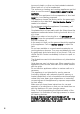
Installation Statutory requirements This installation must conform with the following: Ø Manufacturer’s Installation instructions Ø Local Gas Fitting Regulations Ø Municipal Building Codes, Ø Refer to AS/NZS 5601.1 for Gas Installations. Ø S.A.A. Wiring Code Ø Local Electrical Regulations Ø Any other statutory regulations Preparing to install Refer to AS/NZS 5601.1 for piping size details. These built-in cooktops are intended to be inserted in a benchtop cutout.
Before connecting the unit, check whether the local connection conditions (type of gas) are compatible with the unit’s setting. Observe any special conditions imposed by local suppliers (utilities). The specifications of this cooktop are stated on the data label located on the bottom of the cooktop base. A duplicate data label is supplied for adhesion to an accessible location near the hotplate if the data label on the base of the hotplate cannot be accessed when the hotplate is installed.
. Fig. 2 If an oven is positioned below the cooktop the barrier does not need to be fitted, but a space of 35 mm must be maintained between the underside of the cooktop and the top of the oven. A space of 5 mm must be maintained between the benchtop and the top front part of the oven. See Fig. 2.
. Fig. 3. Connection Electrical Fig. 4 An electrical 10 amp socket needs to be within 1 m of the hotplate to allow electrical connection. The socket must remain accessible after installation of the appliance. Important note: This appliance is connected to the mains (240 VAC) by means of the connecting lead which must be fixed to the kitchen unit to prevent it from coming into contact with hot parts of the cooktop (or an oven installed underneath) and remain accessible after installation of the cooktop.
To find out the factory set gas type, see bottom of cooktop next to gas connection. Remove plastic cap from gas supply line prior to installation. Fit regulator (N.G.) or a test point (Universal LPG) directly to the R 1/2’’ connection as per Fig. 5. and Fig. 6. Direction of gas flow is indicated on the rear of the regulator. For position of the inlet connection refer Fig.1. Use pipe compound or thread sealant, properly theaded pipes and careful assembly procedure so that there is no cross threading, etc.
Before Leaving- Check all connections for gas leaks with soap and water. DO NOT use a naked flame for detecting leaks. Ignite all burners both individually and concurrently to ensure correct operation of gas valves, burners and ignition. Turn gas taps to low flame position and observe stability of the flame for each burner individually and all together. Adhere the duplicate data plate to an accessible location near the hotplate.
Changing the nozzles of the burners on the cooktop - Remove the pan supports, burner covers and diffusers.Fig. 7. Fig. 7 - Change the nozzles using the spanner provided by our Service Centre (code 340847, for double flame burners, taking special care to ensure that the nozzle does not fall when it is removed from the burner or when fitted. Fig. 8. Ensure that it is completely tightened in order to guarantee the seal. Fig. 8 Adjustment of the taps Set the control knobs to minimum.
burn back to the injector when the valve is turned quickcly from ‘Full On’ to the “Minimum flame” position and back a few times. To adjust the minimum flame position for ULPG the screw must be fully tightened down clockwise. If the by-pass screw cannot be accessed, disassemble the grease splash tray, which is fixed to the rest of the hob using a clip and screw mounting system. The following steps must be taken to remove the grease splash tray: - Remove all the burner covers, pan supports and control knobs.
Operating instructions Burner locations 1 2 3 4 5 Pan supports Control knobs Auxiliary burner (up to 1 kW) Semi-rapid burner (up to 1,75 kW) Dual double-flame wok burner (up to 5 kW) The gas burners Operation There are indications to show which burner each control knob operates. Fig. 12. Fig. 12 It is essential to ensure that all the burner parts and pan supports are correctly installed for the appliance to work correctly. Fig.13-14. Fig. 13 Fig.
Switching on automatically If your cooktop can be switched on automatically (ignition sparkers): 1. Press the chosen burner control knob and turn it anticlockwise to the maximum power setting. While the control knob is still pressed down, sparks are produced on all burners. The flame ignites (it is no longer necessary to press down the control knob). 2. Turn the control knob to the required setting. If it does not come on, turn the control knob to the off setting and repeat the steps above.
Inner flame on minimum power. Warnings It is normal to hear a slight whistling noise while the burner is operating. When it is first used, it is normal for the burner to give off odours; this does not pose any risk and does not indicate a malfunction; they will disappear in time. Keep the burner as clean as possible. If the ignition sparkers are dirty they will not light properly. Clean them periodically using a small non-wire brush.
Suitable pans The pans should not exceed the cooker edge in any case. The chart below gives the correct pan usage for each burner Burner Semi-rapid burner Minimum pan diameter Maximum pan diameter 14 cm 20 cm Wok burner Auxiliary burner Accessories 22 cm 12 cm 16 cm Depending on the model, the hob may include the following accessories. These are also available from the Technical Assistance Service.
Cooking recommendation Very high, high Medium Wok burner Boiling, grilling, browning and Asian food (wok). Reheating and keeping things hot: cooked and pre-cooked dishes. Semi-rapid burner Steaming potatoes, Reheating, keeping things hot and fresh vegetables, making tasty casseroles. stews, pasta. Auxiliary burner Casseroles, rice pudding and caramels. Defrosting and slow cooking: vegetables, fruits and frozen products. Low Melting: butter, chocolate and jelly. Do not place anything, eg.
Precautions for use The following advice is intended to help you save energy and prevent pan damage: Use pans which are the right size for each burner. Do not use small pans on large burners. The flame should not touch the sides of the pan. Do not use damaged pans, which do not sit evenly on the cooktop. Pans may tip over. Only use pans with a thick, flat base. Do not cook without using a lid and make sure the lid is properly fitted to avoid wasting energy.
Cleaning and maintenance Cleaning Once the appliance is cool, use a sponge to clean it with soap and water. After each use, clean the surface of the respective burner parts once they have cooled down. If any residue is left (baked-on food, drops of grease etc.), however little, it will become stuck to the surface and more difficult to remove later. The holes and grooves must be clean for the flame to ignite properly. The movement of some pans may leave metal residue on the pan supports.
Service DO NOT MODIFY THIS APPLIANCE. Only authorized personnel from the Service Centre are qualified to work on the appliance. Sometimes certain faults detected can be easily resolved. Before calling the Service Centre, bear in mind the following advice: Fault Possible cause Solution The general electrical system is malfunctioning. Defective fuse. Check the fuse in the main fuse box and change it if it is damaged.
Wiring diagram A. Switch B. Blue wire C. Brown wire D. Terminal E. Ignition module www.bosch-home.com CIF: A-28-893550 ROBERT BOSCH HAUSGERÄTE GMBH & ! : P BH615B9TA '( Test point pressure (kPa) Injectors marks LHF LHR RHF RHR ! 01 85/140 118 90 118 ULPG 12 46/71 67 50 67 33,50 34,60 ,56. In compliance with AS/NZS 3100 and AS 4551:2008 " *+ 77 9 ! 220-240V, 0.