This cooktop is for use with Natural Gas and Universal LPG Leave this instructions with the owner PBH6B5B80A, PBH6B5B60A, PBH6B5B90A USER INSTRUCTIONS INSTALLATION INSTRUCTIONS MAINTENANCE INSTRUCTIONS *0.
en Table of contents [ en] I nst r uct i on manual ( Important safety information . . . . . . . . . . . . . . . 2 For your safety . . . . . . . . . . . . . . . . . . . . . . . . . . . . . . . 2 What to do if you smell gas . . . . . . . . . . . . . . . . . . . . . 2 Warnings . . . . . . . . . . . . . . . . . . . . . . . . . . . . . . . . . . . 2 5 Installation and connection. . . . . . . . . . . . . . . . . 3 Statutory requirements . . . . . . . . . . . . . . . . . . . . . . . . Preparing to install . . .
en bench top wood, plastic or other non-heat resistant materials. Never leave oil or hot fat unattended. The surfaces on heating and cooking appliances get hot when in use. Be careful. Keep children away from the appliance. Only use your appliance for the preparation of food and never for room-heating purposes. This appliance leaves the factory set for the gas supply indicated on the data label. Call the Service Centre if it needs to be altered. Do not tamper inside the appliance.
en a ¸ PLQ PD[ PLQ a a Before connecting the unit, check whether the local connection conditions (type of gas) are compatible with the unit’s setting. Observe any special conditions imposed by local suppliers (utilities). The specifications of this cooktop are stated on the data label located on the bottom of the cooktop base.
en Connection Electrical An electrical 10 amp socket needs to be within 1 m of the hotplate to allow electrical connection. The socket must remain accessible after installation of the appliance. Important notes: ■ This appliance is connected to the mains (240 VAC) by means of the connecting lead which must be fixed to the kitchen unit to prevent it from coming into contact with hot parts of the cooktop (or an oven installed underneath) and remain accessible after installation of the cooktop.
en Converting the cooktop from Nat. Gas to Universal LPG To change injectors All work involved in installation, setting and adaptation to a different gas type must be carried out by authorised personnel from our Service Centre and must comply with current regulations and the conditions laid down by the local gas company. Request change-over injectors from our customer service deparment (refer injector chart below for sizes).
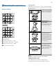
en 1Operating the appliance Burner locations Accessories Depending on the model, the hob may include the following accessories. These can also be acquired from the Technical Assistance Service. Additional support for woks Only when using cookware with a domed base on wok burners. 3%+ % % $ 1 2 Additional support for espresso makers Only when using cookware with a base less than 12 cm in diameter on the smallest burner.
en Operation Remove the plastic covering used to protect the stainless steel before using the appliance (depending on the model). If any traces of adhesive remain on the printed areas, remove them with a wet cloth. There are indications to show which burner each control knob operates. Safety system Depending on the model, your hob may have a safety system (thermocouple) that prevents the flow of gas if the burners accidentally switch off.
en that the room is properly ventilated. Keep natural ventilation openings, such as windows, open or provide a mechanical ventilation device (e.g. a range hood or overhead exhaust fan). An orangy flame is normal and simply indicates the presence of salt in the atmosphere (from cooking). If the flame has yellow patches, this is not a fault (of any kind).
en If the pan supports are fitted with rubber rests, ensure that these are also cleaned. The rests may come loose and the pan support may scratch the hob. Always dry the burners and pan supports completely. Water droplets or damp patches on the hob at the start of cooking may damage the enamel. After cleaning and drying the burners, make sure the burner caps are correctly positioned on the diffuser. Caution! ■ Do not remove the control elements when cleaning the appliance.
en Wiring diagram A B C D E Switch Blue wire Brown wire Terminal Ignition module 11
3PCFSU #PTDI )BVTHFSÉUF (NC) $BSM 8FSZ 4USBF .