Power Xpress™ Bollard Charge Station Installation Guide
Power Xpress™ Bollard Charge Station Installation Guide Technical Support 1-877-805-EVSE (3873) Copyright © 2012 Service Solutions U.S. LLC All rights reserved. The information, specifications, and illustrations in this guide are based on the latest information available at the time of printing. Service Solutions U.S. LLC reserves the right to make changes at any time, without notice. 2 EL-50600-17 Rev.
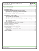
Power Xpress™ Bollard Charge Station Installation Guide TABLE OF CONTENTS INSTALLATION SAFETY...................................................................................................4 INSTALLATION CONTENTS: BOLLARD AND EVSE (EL-50650)............................................5 Power Xpress EVSE (EL-50600-300) for Bollard Charge Station.....................................5 Bollard and Hardware (EL-50600-500)........................................................................
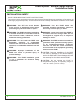
Power Xpress™ Bollard Charge Station Installation Guide INSTALLATION SAFETY SAVE THESE IMPORTANT SAFETY INSTRUCTIONS. This guide contains important instructions that must be followed during the installation of the electric vehicle supply equipment (EVSE). All instructions should be carefully read before installation of the EVSE. WARNING: Turn OFF the circuit breaker at the service or distribution panel before performing any electrical work or repairs.
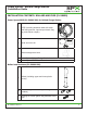
Power Xpress™ Bollard Charge Station Installation Guide INSTALLATION CONTENTS: BOLLARD AND EVSE (EL-50650) Power Xpress EVSE (EL-50600-300) for Bollard Charge Station POWER STATUS EVSE (including attached cable with strain 1 relief and grommet, input/output decals, flag tag, and vehicle coupler) RESET 1 Decal and cover kit 1-877-805-EVSE (3873) http://evse.spx.
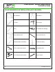
Power Xpress™ Bollard Charge Station Installation Guide TOOLS SUGGESTED FOR INSTALLATION (NOT PROVIDED) Tape measure Wire cutters 2-ft Level Wire stripper Pencil Nonmetallic wire stripper Power hammer drill Masonry drill bit set Small flat-blade screwdriver Needle-nose pliers 7/16-in. Open-end wrench Expandable pliers 1/2-in. Ratchet and sockets Torque wrench 7/16in 6 EL-50600-17 Rev.
Power Xpress™ Bollard Charge Station Installation Guide APPLICABLE ELECTRICAL SYSTEMS IMPORTANT: The on-site service connection must be properly identified before installation of the EVSE. If you are unsure of the available service connection, consult the local utility company or contact Service Solutions US at 1-877-805-EVSE (3873). NOTE: The L1, L2, and ground outputs (H, N for Europe) in the following illustrations correspond to the inputs on the EVSE.
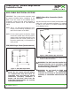
Power Xpress™ Bollard Charge Station Installation Guide 240V 3-Phase Delta Connection (North America) with Center Tap on One Leg One leg must be center-tapped, and only the two phases on either side of the center tap can be used with the delta connection. NOTE: The third line (L3 on the illustration of the delta) is 208V, with respect to the neutral, and is sometimes referred to as a “stinger.” WARNING: Do not use this third line.
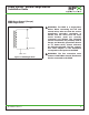
Power Xpress™ Bollard Charge Station Installation Guide 230V Above Ground (Europe) 230V Single Phase LINE (H) 230VAC NEUTRAL (N) EARTH Figure 4. 230V Single Phase EL-50600-17 Rev. A WARNING: The EVSE is a single-phase device. When connecting the line and neutral wires, take care that the service transformer secondary connection is known, and the wires from the main circuit breaker panel are correctly connected and labeled.
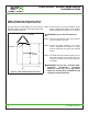
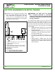
Power Xpress™ Bollard Charge Station Installation Guide ELECTRICAL REQUIREMENTS FOR BATTERY CHARGING CAUTION: The AC electrical connection must have a grounded, dedicated service-main. No other loads shall be connected to the same circuit. Use of a non-dedicated circuit could exceed the current rating of the circuit breaker and cause it to trip or open. G H A F 6 in. B C D 18 in. 24 in. E A. Conduit extending up to 24 in. (61 cm) from ground level or per local code B. Conduit sweep C.
Power Xpress™ Bollard Charge Station Installation Guide AMPERAGE AND BREAKER PARAMETERS: FIELD REQUIREMENTS AND ADJUSTMENTS FOR EVSE INSTALLATION (NOT REQUIRED FOR 40 AMP CIRCUIT INSTALLATION) 1. Unpack the EVSE. A D C B A. EVSE body B. EVSE cable C. Strain relief with grommet D. 18 in. (46 cm) Figure 6. EVSE NOTE: The EVSE has been factory set at 30 amp output for a 40 amp circuit. Proceed to “Standard Installation” if installing on a 40 amp circuit.
Power Xpress™ Bollard Charge Station Installation Guide Figure 8. Current-Adjustment Settings 12 EL-50600-17 Rev.
Power Xpress™ Bollard Charge Station Installation Guide STANDARD INSTALLATION 1. Lay down the bollard box and remove the banding. 2. Lift the top off the box and remove the bollard from the packaging material. 3. Remove the upper cover from the bollard assembly by removing the cable-management retaining screws (E) on the rear of the bollard. 4. Remove plastic bag containing locating set screw (not shown) from inside bollard.
Power Xpress™ Bollard Charge Station Installation Guide CAUTION: Read all instructions before installing the EVSE. WARNING: Main service power must be off and disconnected before attempting to install the EVSE. WARNING: The bollard weighs 20 lb per foot, and the bottom end is significantly heavier than the top end. Take proper precautions and use safe lifting practices when lifting the bollard. CAUTION: All adapter and connection fittings must be classified as liquid-tight.
Power Xpress™ Bollard Charge Station Installation Guide 5. Place the bollard on its side. 6. Gently guide the conduit through the bottom of the bollard and position the bollard over the bolts and onto the base. 10. Install a washer, lock washer, and nut on each bolt. A A B D C A. 1/2-in. liquid-tight flexible conduit B. Liquid-tight fitting C. Adapter D. Bollard base plate Figure 14. Guide Conduit into Bollard 7.
Power Xpress™ Bollard Charge Station Installation Guide 12. Position the conduit on the left side of the bollard (opposite the open metal slot side). 14. Mark 1/2-in. liquid-tight flexible conduit for length based on the required radius bend to attach to the top of the EVSE. B A B C A A. Location to cut conduit B. Precut hole in top of EVSE C. 1/2-in. liquid-tight flexible conduit Figure 19. Location to Cut Conduit A. Tapered EVSE guide bracket B. 1/2-in. liquid-tight flexible conduit Figure 17.
Power Xpress™ Bollard Charge Station Installation Guide NOTE: All connections must be liquid-tight. 17. Feed wires into the hole in the top of the EVSE and attach 1/2-in. liquid-tight flexible conduit with a liquid-tight fitting. 19. Strip wires and wire them into the EVSE. Refer to label on inside of EVSE cover or details on circuit board. Torque terminal screws to 10.62 ± 1 in-lb (1.2 ± 0.12 Nm). A B C Figure 22. Wires Installed into EVSE A. 1/2-in. liquid-tight flexible conduit B.
Power Xpress™ Bollard Charge Station Installation Guide 21. Apply decal to the front of the EVSE cover. 22. Continue lowering the EVSE until the front edge of the EVSE bottom cover rests on the ledge in the bollard front opening. 23. Push any excess conduit down into the bollard. A loop will extend above the bollard and fit in the top cover. A B A. EVSE bottom cover B. Ledge in bollard front opening Figure 24. EVSE Lowered into Position Figure 25. Excess Conduit Pushed into Bollard 24.
Power Xpress™ Bollard Charge Station Installation Guide 25. Position the strain relief at the bottom of the side slot metal mounting bracket in the steel bollard. Position such that the rubber grommet (D) seats on the opening of the lower plastic bollard cover. 26. Tighten the inner strain-relief nut (A) inside the bollard hand tight. Using expandable pliers, tighten the nut an additional 1/4 turn. A B D Figure 28. Tightening the Strain-Relief Nut C NOTE: Do not overtighten the strain-relief nut.
Power Xpress™ Bollard Charge Station Installation Guide 27. Carefully lower the upper plastic cover down onto the bollard base. 28. Use a small flat-blade screwdriver or similar tool to guide the upper plastic cover into the seal. 5.AFT ER SAFE TY TEST VEHIC LE IS VERIF CHAR ICATION GING - STATU T COMP . S LIGHT LETIO STATUS. N OF BEGINS CHAR TO FLAS 7.UNP G - STAT LUG VEHIC H GREE US LIGHT N, INDIC INDIC LE COUP RETU ATOR ATING RNS TO LER CHAN 8.
Power Xpress™ Bollard Charge Station Installation Guide 31. Loop the cable onto the cable-management holder. Figure 31. Cable Looped on Hook 32. Switch the main circuit breaker to the ON position and verify that the Power LED is illuminated solid green and the Status LED is illuminated solid amber on the EVSE. Figure 32. Complete Installation EL-50600-17 Rev.
Power Xpress™ Bollard Charge Station Installation Guide EVSE POWER AND STATUS LED INDICATIONS POWER LED STATUS LED CONDITION (OFF) (OFF) NO SERVICE SUPPLY POWER GREEN SOLID AMBER SOLID EVSE POWERED; VEHICLE COUPLER NOT CONNECTED GREEN SOLID GREEN SOLID WAITING TO CHARGE GREEN SOLID GREEN BLINKING VEHICLE IS CHARGING GREEN SOLID 1 OR 2 RED BLINKS EVERY 2 SECONDS PILOT CHARGING ERROR* GREEN SOLID SOLID RED THEN GREEN BLINK EVERY 2 SECONDS GROUND FAULT DETECTED* GREEN SOLID RED BLINKING
Power Xpress™ Bollard Charge Station Installation Guide TROUBLESHOOTING If there is a charging issue proceed with the following steps. If the issue persists after three attempts call Service Solutions U.S. LLC at 1-877-805-EVSE (3873) for assistance. Problem Indicated by LED Status Solution Pilot charging error 1. 2. 3. Ground fault detected 1. 2. 3. 4. 5. Ground monitor interrupted 1. 2. 3. 4. 5. Operation fault 1. 2. 3. EL-50600-17 Rev. A Verify supply-side power.
Power Xpress™ Bollard Charge Station Installation Guide Ground Fault Circuit Interrupt (GFCI) Tripped If the EVSE detects a ground fault, power will be interrupted and the STATUS LED will illuminate (red flash with intermittent green). The EVSE will attempt to reset automatically and re-attempt charging (see note below on European models). If the fault condition persists after an initial automatic attempt, per the code, the EVSE waits 15 minutes before a second attempt is made.
Power Xpress™ Bollard Charge Station Installation Guide LIMITED WARRANTY THIS WARRANTY IS EXPRESSLY LIMITED TO THE ORIGINAL PURCHASER OF SERVICE SOLUTIONS U.S. LLC EVSE PRODUCT. • Power Xpress Bollard is warranted against defects in materials and workmanship for one year from the date of installation. • EVSE Cables and Connectors are warranted against defects in materials and workmanship for 90 days from the date of delivery.
EL-50600-17 Rev. A © Service Solutions U.S.