
Specifications

Connect a module using the plug-in module connector or using a B450 Conettix Plug-in
Communicator Interface
(refer to the Conettix Plug-in Communicator Interface (B450)
Installation and Operation Guide and B450 Conettix Plug-in Communicator Interface, page 50).
This section includes basic installation instructions. For detailed instructions, refer to the
corresponding Conettix plug-in module document listed in Optional module documents, page
12.
Supervision
The control panel supervises a plug-in cellular communicator when the control panel uses the
module in any of the four route groups as part of either the primary route or the backup route,
and the control panel uses the module to route any personal notifications. Supervision
ensures reliable operation between the module and the control panel.
If supervised and the module does not respond to control panel supervision polls, then a
system fault message shows on the keypads. The control panel sends a corresponding report
to the central station.
Installation and module wiring (B44x)
Ensure that there is enough power for the module and other powered devices you want
connected to the system.
Refer to On-board outputs, page 60.
!
Caution!
Remove all power (AC and battery) before making any connections. Failure to do so might
result in personal injury and/or equipment damage.
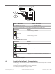
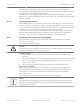
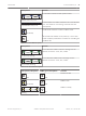
Install the module
The module plugs into a connector and is held in place with a plug-in module retention clip.
The module handle and support on top of the module hold the unit during installation.
Plug the module in to a control panel by aligning the module with the control panel’s on-board
connector. The retention clip has a locking device to help hold the card in position. Pull the
locking device back. Slide the module down until it seats firmly into the connector slot. The
locking handle will then click into pace holding the module in the socket.
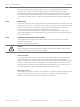
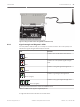
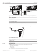
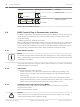
Wire to the antenna
The module has a threaded connector for connection to an antenna. Route the antenna cable
through a wire knockout in the top of the enclosure. Connect the antenna cable to the
module. Secure the antenna cable to the outside of the enclosure.
8.2.1
8.2.2
44 en | IP communications Control Panel
2014.05 | 11 | F.01U.287.180 Installation and System Reference Guide Bosch Security Systems, Inc.