
Specifications


!
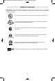
Wheel guard must be
attached when using cutting
wheels. Always keep wheel guard be tween
you and your work while cutting.
9%6(409+ 7,390( %0;%=7
&) %88%',)( ;,)2:%'991
,37)-7 238'322)'8)( Wheel bursting may
eject wheel fragments towards user if guard
plug is not attached.
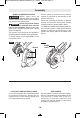
The position of the guard can be adjusted to
accommodate the operation being performed.
To attach wheel guard DISCONNECT tool
from power source.
Position guard on spindle neck so that the
notches on guard line up with the keys on the
spindle neck (Fig. 2).
Rotate the guard either direction to desired
position, and move the locking lever into the
LOCKED position to secure guard in place.
TO REMOVE GUARD: Move locking lever into
the unlocked position, rotate guard until the
notches on guard line up with the keys on the
spindle neck, and lift guard off the spindle neck
(Fig. 2).
77)1&0=
-10-
Your tool is equipped with a threaded spindle
for mounting ac ces sories. Always use the
supplied lock nut (and backing flange) that
has same thread size as spindle.
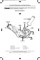
The side handle is used to control and balance
the tool. The handle must be thread ed into the
front housing on either side of the tool,
depending on per sonal preference and
comfort. Use the side handle for safe control
and ease of operation (Fig. 1).
!
WARNING
!
WARNING
FIG. 2
KEYS
NOTCHES
LOCKING
LEVER
FIG. 3
BM 2610008432 08-10:BM 2610008432 07-10 7/29/10 10:08 AM Page 10