
Technical data


2
Introduction
Please read these installation instructions completely
and carefully. They will save you time and effort and
help to ensure optimum dishwasher performance. Be
sure to observe all listed warnings and cautions.
These installation instructions are intended for use by
qualified installers. In addition to these instructions the
dishwasher shall be installed:
* In the United States, in accordance with the
National Electric Code/State and Municipal codes
and/or local codes.
• In Canada, in accordance with the Canadian Electric
Code C22.1 - latest edition/Provincial and
Municipal codes and/or local codes.
These shall be carefully followed at all times.
If the dishwasher is a new installation most of the work
must be done before the dishwasher is moved into place.
If the dishwasher is replacing another dishwasher the
connections for the dishwasher being replaced must be
checked for compatibility with the new dishwasher and
replaced as necessary.
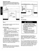
Tools Needed for Installation
Refer to Figure 1:
A. Tape Measure
B. Flat blade screwdriver
C. Phillips screwdriver
D. Torx screwdriver, #20
E. Electric Drill
E Hole saw or 1" hole cutter
G. Hammer
H. Level
I. Open end wrench
J. Adjustable wrench, 2 reqd.
K. Pipe wrench, 2 reqd.
L. Wire Cutter
M. Wire stripper
Materials You Will Need
• Minimum 3/8" O.D. copper tubing of sufficient
length for your installation.
• Shut-off valve and fittings for hot water supply line.
• 90 ° elbow with 3/8" N.P.T. external threads on one
end and sized to fit your water supply line on the
other end.
• Teflon tape or other pipe sealant.
• 3 twist-on wire connectors for 16 AWG wire.
• UL listed conduit connector or strain relief.
Additional materials may be required to comply with
local codes.
O
)
Figure 1.
Accessory Parts Supplied
Check to make sure that the accessory parts supplied for
your model, see Figure 2, are all there. If any parts are
missing contact your dealer immediately.
Refer to Figure 2:
O. Cover Plugs (2)
E Screws (2), for terminal box cover/toe panel
R. Mounting brackets (2)
S. Wood screws (2)
T. Drain hose clamps (2) with rubber connection hose (1)
U. Screws, M6 x 26 (2)
V. Mounting brackets (4) and screws (8)
W. Template sheet with instruction pictograms.
X. Screws, M4 x 42 (2) (SHV models only)
Y. Handle Installation Kit with Instructions (SHU 9900
models only)
Accessory parts supplied with:
SHU models SHI and SHV models
_-C_ _
O__
0-44
Figure 2.