9000 965 903 Rev D (9412) Installation Instructions Notice d’installation Instrucciones de instalación
Important Safety Instructions: Please READ and SAVE this information To avoid possible injury or property damage, OBSERVE ALL WARNINGS AND CAUTIONS. These instructions are intended for use by qualified installers only. The dishwasher must be installed by a qualified service technician or installer. • In addition to these instructions, the dishwasher shall be installed to meet all electrical and plumbing codes and ordinances (both national and local).
WARNING Avoiding General Hazards Do not use the dishwasher until it is completely installed. When opening the door on an uninstalled dishwasher, carefully open the door while supporting the rear of the unit. Failure to follow this warning can cause the dishwasher to tip over and result in serious injury. Before installing the supplied counter top mounting brackets, decide which method will be used to secure the dishwasher into its opening.
This appliance must be connected to a grounded metal, permanent wiring system, or an equipment-grounding conductor must be run with the circuit conductors and connected to the equipment-grounding terminal or lead on the appliance. Do not use extension cords. Avoiding Plumbing/Scalding Hazards Do not perform any work on a charged hot water line. Serious injury could result. Only qualified plumber should perform plumbing work.
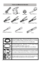
Tools and Materials Needed Adjustable Wrench Wire Cutter Phillips Screwdriver Drill Wire Stripper Hole Saw Pliers Slot Screwdriver Tape Measure Needle Nose Pliers Level Electrical Supply Cable - Minimum #14 AWG, 2 conductor, 1 ground, insulated copper conductors rated 75°C or higher Only needed if house electrical line is not adequate. Hot Water Supply Line - Minimum 3/8″ O.D.
Materials supplied (all models) A Junction Box B Edge Protector C Screw Clamp (for drain hose) D Mounting Brackets E Mounting Bracket Screws Ø 4x13 mm F Adhesive Backed Cord Clip 5
Materials supplied (model dependent) Installation Guide for Fully Integrated Door Panel (model dependent) G Slotted Toe Panel (model dependent) H Slotted Toe Panel Screws Ø 4x16 mm (model dependent) I J K 6 Non-Slotted Toe Panel (model dependent) Non-Slotted Toe Panel Screws (model dependent) - Black or silver depending on toe panel color Toe Panel Mounting Brackets (model dependent and only used with non-slotted toe panel shown above)
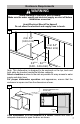
Enclosure Requirements WARNING Avoid Scalding or Electrical Shock Hazard! Make sure the water supply and electrical supply are shut off before installation or service. Avoid Electrical Shock/Fire Hazard! Do not allow the electrical and supply lines to touch. 1 min 24" (610 mm) min 34" (864 mm) 235/8" - 241/4" (600 - 616 mm) Note: This dishwasher is designed to be enclosed on the top, back and both sides by standard residential kitchen cabinetry.
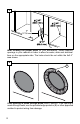
3 7" (177.8 mm) After locating the proper place for your dishwasher, create required openings in your cabinets in order to allow for water, drain and electrical lines on the appropriate side. The holes should be cut within the 4x2.5” area shown. 4 B If the opening is made through wood, sand it smooth. If the opening is made through metal, use the provided edge protector (B) or other approved method to protect wiring from damage.
5 1 2 Twist the end of the water supply line to detach from the dishwasher base as shown. 6 Pull the drain hose out of the packaging base as shown. Set toe panel aside for later use.
7 REMOVE THIS TAG BEFORE INSTALLATION RETIRER CETTE ÉTIQUETTE AVANT L'INSTALLATION Important Information Route the hoses through the left or right hand side traps. Refer to installation guide for details. Information importante Faites passer les tuyaux par le collier de gauche ou de droite. Consultez le guide d'installation pour les détails. Remove the hose hanger clip and hanger label at the back of the dishwasher as shown above.
Dishwasher Electrical Rating Volts Hertz Amperes Watts 120 60 12 15 1,440 1,450 (max) Grounding Instructions The dishwasher must be properly grounded before operating. This appliance must be connected to a grounded metal permanent wiring system or an equipment grounding conductor must be run with the circuit conductors and connected to the equipment grounding terminal or lead on the dishwasher.
9 ADVERTENCIA ESTRICTAMENTE SIGA TODAS LAS INSTRUCCIONES DE ESTE MANUAL. UTILICE SÓLO EL 14 O 12 DE ALAMBRE DE COBRE AWG CON UN GRADO DE LA TEMPERATURA MÍNIMA DE 75 ° C (167 ° F). COLOQUE TODOS LOS CABLES EN LA CAJA DE LA FUENTE DE ALIMENTACIÓN Y LA INSTALACIÓN DE LA CUBIERTA. TORNILLOS DE CONEXIÓN NO SON EXTRAIBLES. arrow 1/2" (13 mm) WIRE STRIP GAGE CALIBRE DE POUR DÉNUDER INDICADOR DE CABLE PELADO WARNING STRICTLY FOLLOW ALL INSTRUCTIONS IN THIS MANUAL. USE ONLY 14 OR 12 AWG COPPER WIRE WITH A MIN.
10 A Route supply cord through opening into dishwasher cabinet. 11 Strap Alterna te cable ro uting Clip ori entation CLICK 5" (127 m m) Leg Adjuster Adhesive backed cord clip Place adhesive backed cord clip (provided in the installation kit) 5" (127 mm) from leg adjuster as shown in the figure above and route power cord through the clip. Note: The length of cord measured from the plastic back strap to the receptacle should be ≤ 47.25" (1,200 mm).
Installation of Mounting Brackets NOTICE Before installing the supplied counter top mounting brackets, decide which method of securing the dishwasher into its enclosure will be used. Once the mounting brackets are installed on the dishwasher, removing them is difficult and will damage the mounting brackets and the dishwasher. If you have a Fully Integrated Panel, do not attach mounting brackets until after attaching the panel to the door.
13 Side Mount is used for counter tops made of marble, granite, or other very hard materials that cannot be easily drilled. Grasp mounting bracket (D) with pliers at perforation and bend until rounded end breaks free. Discard end. Slip bracket flange through side slots in frame as shown. Using pliers, bend flange such that the bracket will not slip out of slot. Do not attach to cabinet yet.
Positioning the Dishwasher 14 If your sink is to the right side of where you are installing the dishwasher, you will need to reposition the hoses behind the dishwasher before installing. To do so, unhook the strap that the hoses are running through on the back of the dishwasher base and position them per your requirements. If your sink is to the left side, leave the hoses as they came and skip to step 16.
15 Reposition the hoses such that they run through the strap on the other side. Be sure to snap the strap back in place to secure the hoses as shown. 16 To avoid scratching the floor, use floor protection and caution when sliding the dishwasher into the cabinet. Use hands on both sides of dishwasher to push evenly. Pull water inlet and drain hoses through the hole in cabinet as shown.
17 Push the unit 2/3 of the way into the opening and stop. 18 Reach into adjacent cabinet and pull hoses and excess power cord completely out so they do not get kinked. Push the unit in until flush with cabinet door.
11 /1 6 19 Adjust the legs as shown to raise the unit so it is flush with the counter. Use a level to check that your dishwasher is level. Level side to side by turning feet clockwise to raise or counter-clockwise to lower front of the unit as shown. Level front to back by turning center screw clockwise to raise or counterclockwise to lower the back. 20 Center the dishwasher in the opening before securing it to your cabinet or counter top as shown.
Securing the Dishwasher 21 E 22 E Drive the mounting screws (E) through the holes in the mounting brackets as shown for Top (21) or Side Mount (22).
Water Inlet Connections WARNING Avoid Scald Hazard Do not perform any work on a charged hot water line. Serious injury could result. Only qualified plumbers should perform plumbing work. Do not attempt any work on the dishwasher hot water supply plumbing until you are certain the hot water supply is shut off. NOTICE Temperatures required for soldering and sweating will damage the dishwasher. If plumbing lines are to be soldered or sweated, keep the heat source at least 6 inches (152.
23 Connect the dishwasher water supply line to the water shut off valve. You will need to use an approved dishwasher water supply line with the correct fittings for this connection. Always use the appropriate seal when making plumbing connections. After all connections are made, turn on the hot water and check for leaks. Drain Connections IMPORTANT NOTES about your drain connection: • If local ordinance requires an air gap, install it according to the manufacturer’s instructions.
NOTE: Place hose clamp around end of drain hose BEFORE connecting to the plumbing. 24 b a C C The dishwasher drain hose may be connected to the drain plumbing using an air gap in one of two ways: - Connect to the under sink dishwasher drain connection (24a). - Connect to a disposer dishwasher drain connection (24b).
25 Use the clamp provided (C) to attach the drain hose to the house plumbing as shown. C Attaching the Toe Panel 26 H G If your dishwasher came with a slotted toe panel (G), follow these instructions; otherwise skip to 27 now. Note: If using the slotted toe panel shown in 26 above, then metal mounting brackets shown in 27 are not required. Position the slotted toe panel (G) on the dishwasher. Allow it to rest on the floor.
J K If your dishwasher came with a non-slotted toe panel (I) and toe panel brackets (K), follow these instructions: Plug metal brackets (K) into openings on both sides of the base as shown. Use screw (J) to mount metal brackets to the base as shown. 28 Tuck the pre-attached rubber apron behind the fingers on the metal brackets as shown.
29 J Slide metal toe panel into position ensuring the bottom of the toe panel is flush with the floor. Use screw (J) to mount the toe panel through the hole it matches up with on the metal brackets (K) as shown. Note: The toe panel height can be adjusted by screwing into a different hole in the bracket. Check for correct fit of apron by opening the door. Ensure the apron does not bind up and can freely move up and down behind the toe panel.
Customer Service Your dishwasher requires no special care other than that described in the Care and Maintenance section of the Use and Care Manual. If you are having a problem with your dishwasher, before calling for service please refer to the Self Help section in the Use and Care Manual. If service is necessary, contact your dealer or installer or an authorized service center. Do not attempt to repair the appliance yourself. Any work performed by unauthorized personnel may void the warranty.
Consignes de sécurité importantes: Veuillez LIRE et CONSERVER ces informations Afin d’éviter toute possibilité de blessures ou de dommages matériels VEUILLEZ OBSERVER TOUS LES AVERTISSEMENTS ET PRÉCAUTIONS. Ces instructions sont destinées uniquement à l’usage des installateurs qualifiés. L’installation du lave-vaisselle doit être effectuée par un technicien de maintenance ou un installateur qualifié.
AVERTISSEMENT Prévention des dangers d’ordre général Ne pas utiliser le lave-vaisselle tant que l’installation n’est pas complètement terminée. Pour ouvrir la porte d’un lave-vaisselle dont l’installation n’est pas terminée, agir avec prudence et en soutenant la partie arrière de l’appareil. Le non respect de cet avertissement peut entraîner le basculement du lave-vaisselle et provoquer de graves blessures.
Le client a la responsabilité de vérifier que l’installation électrique du lavevaisselle est conforme à tous les codes et ordonnances électriques nationaux et locaux. Le lave-vaisselle a été conçu pour fonctionner avec une alimentation électrique en courant alternatif de 120 volts, 60 Hz, connectée à un circuit électrique correctement mis à la terre, adapté au lave-vaisselle, avec protection par fusible ou disjoncteur d’une puissance de 15 ampères.
Outils et pièces nécessaires Clé ajustable Pince coupante Tournevis Perceuse Scie cylindrique Pince à dénuder Tournevis Pince Ruban à mesurer Needle Nose Pliers Niveau à bulle Câble d’alimentation électrique - calibre de 14 AWG minimum, deux conducteurs, 1 mise à la terre, conducteurs en cuivre isolé à une température nominale de 75 °C ou plus. Nécessaire seulement si la ligne électrique de la maison est inadéquate.
Matériel fourni A Boîte de jonction B Gaine de protection flexible pour fil électrique C Collier à vis (pour flexible) D Pattes de fixation E Vis des pattes de fixation Ø 4x13mm F Dos adhésif clip cordon 5
Matériel fourni (selon le modèle) Guide d’installation pour un panneau de porte pleinement intégré (selon le modèle) G H I J K 6 Panneau de plinthe à fentes (selon le modèle) Vis pour le panneau de plinthe à fentes de 4 x 16 mm (selon le modèle) Panneau de plinthe sans fente (selon le modèle) Vis pour le panneau de plinthe sans fente (selon le modèle) - Noir ou argent en fonction de la couleur du panneau de plinthe Pattes de fixation du panneau de plinthe (selon le modèle en fonction et n’être u
Exigences d’encastrement AVERTISSEMENT Évitez les brûlures ou les risques de secousse électrique ! S’assurer que l’alimentation d’eau et l’alimentation électrique sont mises à l’arrêt avant toute installation ou réparation. Evite Descarga Eléctrica / Peligro de incendio! No permita que las líneas eléctricas y de suministro para tocar.
3 7" (177.8 mm) Après avoir choisi un endroit approprié pour votre lave-vaisselle, créer les ouvertures requises pour les connexions d’eau, d’évacuation et d’électricité sur le côté approprié. Les trous devraient être effectués dans la zone de 100 mm x 50 mm (4 x 2 po) illustrée. 4 B Si l’ouverture est percée dans du bois, poncer les rebords du trou.
5 Faire tourner le bout de la conduite d’alimentation en eau pour la détacher de la base du lave-vaisselle, tel qu’illustré. 6 Retirer le tuyau d’évacuation de l’emballage de la base tel qu’illustré. Mettre le panneau de plinthe de côté pour plus tard.
7 REMOVE THIS TAG BEFORE INSTALLATION RETIRER CETTE ÉTIQUETTE AVANT L'INSTALLATION Important Information Route the hoses through the left or right hand side traps. Refer to installation guide for details. Information importante Faites passer les tuyaux par le collier de gauche ou de droite. Consultez le guide d'installation pour les détails. Retirer le collier de serrage du tuyau à l’arrière du lave-vaisselle tel qu’illustré.
Caractéristiques électriques du lave-vaisselle Volts Hertz Amperes Watts 120 60 12 15 1,440 1,450 (max) Instructions de mise à la terre Cet appareil doit être raccordé à un système de câblage en métal permanent mis à la terre ou un conducteur de mise à la terre du matériel doit être utilisé avec les conducteurs du circuit et raccordé à la borne de mise à la terre de l’appareil ou au fil conducteur du lave-vaisselle.
9 ADVERTENCIA ESTRICTAMENTE SIGA TODAS LAS INSTRUCCIONES DE ESTE MANUAL. UTILICE SÓLO EL 14 O 12 DE ALAMBRE DE COBRE AWG CON UN GRADO DE LA TEMPERATURA MÍNIMA DE 75 ° C (167 ° F). flèche COLOQUE TODOS LOS CABLES EN LA CAJA DE LA FUENTE DE ALIMENTACIÓN Y LA INSTALACIÓN DE LA CUBIERTA. TORNILLOS DE CONEXIÓN NO SON EXTRAIBLES. 1/2" (13 mm) WIRE STRIP GAGE CALIBRE DE POUR DÉNUDER INDICADOR DE CABLE PELADO WARNING STRICTLY FOLLOW ALL INSTRUCTIONS IN THIS MANUAL. USE ONLY 14 OR 12 AWG COPPER WIRE WITH A MIN.
10 A Route cordon d’alimentation à travers un lave-vaisselle dans l’ouverture de l’armoire. 11 sangle un routa ge alte rnatif d u câble Clip ori entation CLIC 5" (127 m m) jambe de réglage Adhésif backed clip cordon Placez clip cordon de colle de (fourni dans le kit d’installation) 5" (127 mm) de jambe de réglage comme indiqué sur la figure ci-dessus et de la puissance de l’itinéraire cordon à travers le clip.
Installation des pattes de fixation AVIS Avant d’installer les pattes de fixation pour comptoir fournies, déterminer quelle méthode sécuritaire doit être utilisée pour installer le lave-vaisselle dans son emplacement. Une fois les pattes de fixation installées sur le lave-vaisselle, il sera difficile de les retirer sans les abîmer ou sans abîmer le lave-vaisselle. Si vous avez un panneau entièrement intégré, ne pas installer les pattes de fixation avant d’avoir fixé le panneau à la porte.
13 La méthode de fixation latérale est utilisée pour les comptoirs en marbre, granite ou autres matériaux très durs qui sont difficiles à percer. Prendre chaque patte de fixation (D) avec des pinces au niveau de la perforation et les plier jusqu’à ce que l’embout arrondi se casse. Jeter l’embout. Glisser les rebords des pattes dans les fentes latérales de l’armature tel qu’illustré. À l’aide de pinces, plier les rebords de façon à ce que les pattes ne puissent pas sortir des fentes.
Positionner le lave-vaisselle 14 Si votre évier se trouve à la droite de l’endroit où vous installez le lavevaisselle, vous devrez repositionner les tuyaux derrière le lave-vaisselle avant l’installation. Pour y parvenir, vous pouvez décrocher l’attache des tuyaux à l’arrière du lave-vaisselle et les repositionner en fonction de vos besoins. Si votre évier se trouve à gauche, vous pouvez laisser les tuyaux en place.
15 Repositionner les tuyaux pour qu’ils passent par l’attache et de l’autre côté. S’assurer de remettre l’attache en place pour bien fixer les tuyaux en place tel qu’illustré. 16 Protéger la surface du sol pour éviter les rayures et faire glisser le lavevaisselle à l’intérieur de l’armoire avec prudence. Utiliser les mains sur les deux côtés du lave-vaisselle pour pousser l’appareil de façon égale. Tirer les tuyaux d’alimentation et d’évacuation de l’eau par le trou dans l’armoire tel qu’illustré.
17 Pousser l’appareil aux 2/3 de sa position finale dans l’ouverture avant d’arrêter. 18 Accéder à l’armoire adjacente et tirer les tuyaux et toute longueur excédentaire du cordon d’alimentation pour éviter les nœuds. Pousser l’appareil jusqu’à ce qu’il soit au niveau avec la porte de l’armoire.
11 /1 6 19 Ajuster les pattes tel qu’illustré pour soulever l’appareil et le mettre à niveau avec le comptoir. Utiliser un niveau pour vérifier que le lave-vaisselle est bien au niveau. Mettre le lave-vaisselle à niveau des deux côtés en tournant les pieds dans le sens des aiguilles d’une montre pour soulever l’avant de l’appareil ou en sens inverse des aiguilles d’une montre pour l’abaisser.
Sécuriser le lave-vaisselle 21 E 22 E Insérer les vis de fixation (E) dans les trous des pattes de fixation tel qu’illustré pour l’installation avec fixation supérieure (21) ou latérale (22).
Raccordements d’arrivée d’eau AVERTISSEMENT Évitez les brûlures ou les risques de secousse électrique ! Ne pas tenter de travailler sur une conduite d’eau chaude chargée. De graves blessures pourraient survenir. Seuls les plombiers qualifiés doivent effectuer des travaux sur la tuyauterie. Ne tentez pas d’intervenir sur la tuyauterie d’alimentation d’eau chaude du lave-vaisselle tant que vous n’êtes pas certain que l’alimentation d’eau chaude est coupée.
23 Brancher la conduite d’alimentation en eau du lave-vaisselle à la soupape d’arrêt d’eau. Vous devez utiliser un conduit d’eau pour lave-vaisselle homologué avec les raccords adéquats pour effectuer ce branchement. Toujours utiliser les joints appropriés pour effectuer les raccordements de tuyauterie. Une fois tous les raccordements effectués, ouvrir l’alimentation en eau chaude et vérifier s’il y a des fuites.
REMARQUE : Placer la bride du tuyau autour de l’extrémité du tuyau d’évacuation AVANT de le brancher à la tuyauterie. 24 a b C C Le tuyau d’évacuation du lave-vaisselle peut être branché sur la tuyauterie d’évacuation à l’aide d’un entrefer de l’une des deux manières suivantes : - En le branchant au raccord d’évacuation de lave-vaisselle sous l’évier (24a). - En le branchant au raccord d’évacuation de lave-vaisselle d’un broyeur (24b).
25 Utiliser la bride fournie (C) pour fixer l’adaptateur de tuyau d’évacuation à la tuyauterie résidentielle tel qu’illustré. C Fixation du panneau de pointe 26 H G Si votre lave-vaisselle comprend un panneau de plinthe à fentes (G), suivre les instructions suivantes; sinon passer à l’étape 27.
27 J K Si votre lave-vaisselle comprend un panneau de plinthe sans fente (I) et des pattes de fixation de panneau de plinthe (K), suivre les instructions suivantes : Placer les pattes de fixation métalliques (K) dans les ouvertures des deux côtés de la base tel qu’illustré. Utiliser la vis (J) pour fixer les pattes de fixation métalliques à la base tel qu’illustré. 28 Placer le tablier en caoutchouc préinstallé derrière les crochets des pattes de fixation métalliques tel qu’illustré.
29 J Glisser le panneau de plinthe métallique en position en vous assurant que le bas du panneau est au niveau par rapport au sol. Utiliser la vis (J) pour fixer le panneau de plinthe par le trou pour qu’il soit aligné avec les pattes de fixation métalliques (K) tel qu’illustré. Remarque : La hauteur du panneau de plinthe peut être ajustée en le vissant dans un trou différent de la patte de fixation. Vérifier que le tablier est installé convenablement en ouvrant la porte.
Service après-vente Votre lave-vaisselle ne nécessite aucun entretien particulier autre que celui décrit dans la section « Nettoyage et entretien » du Guide d’Utilisation et d’Entretien. Si vous avez des problèmes avec votre lave-vaisselle, avant d’appeler un service d’entretien et de réparation, consultez la section d’auto-assistance de votre guide. Si un dépannage s’avère nécessaire, communiquez avec votre marchant ou avec l’installateur ou adressezvous à un centre de service agréé.
Instrucciones de seguridad importantes: Por favor lea y guarde esta información Para evitar posibles lesiones o daños materiales, RESPETE TODAS LAS ADVERTENCIAS Y PRECAUCIONES. Estas instrucciones están diseñadas para ser usadas únicamente por instaladores calificados. La lavadora de platos debe ser instalada por un técnico de servicio técnico o instalador calificado.
ADVERTENCIA Cómo evitar peligros generales Use la lavadora de platos únicamente cuando esté completamente instalada. Al abrir la puerta de una lavadora de platos que no está instalada, abra la puerta con cuidado mientras sostiene la parte posterior de la unidad. No seguir esta advertencia puede provocar que la lavadora de platos se caiga, lo que ocasiona lesiones graves.
Asegúrese de que la instalación eléctrica se haya realizado correctamente. No debe haber conexiones eléctricas sueltas. Asegúrese de que todas las conexiones eléctricas se hayan realizado correctamente. El cliente tiene la responsabilidad de asegurarse de que la instalación eléctrica de la lavadora de platos cumpla con todos los códigos y las ordenanzas de electricidad nacionales y locales.
Herramientas y materiales necesarios Clé ajustable Pince coupante Perceuse Pince à dénuder Destornillador Phillips Scie cylindrique Alicates Destornillador de ranura Ruban à mesurer Alicates Niveau à bulle Cable de suministro eléctrico: AWG n.° 14 como mínimo, 2 conductores con 1 conexión a tierra, conductores de cobre aislados, con capacidad nominal para 75 °C o más. Únicamente se necesita si la línea eléctrica de la vivienda no es adecuada.
Materiales suministrados A Caja de empalme B Arandela protectora de borde flexible para cable eléctrico C Abrazadera de tornillo (para mangueras) D Soportes de montaje E Tornillos para los soportes de montaje Ø 4x13mm F Adhesivo respaldado clip de la cuerda 5
Materiales suministrados (depende del modelo) Guía de instalación para panel de puerta completamente integrado (depende del modelo) G Panel de pie con ranuras (depende del modelo) H Tornillos del panel de pie con ranuras Ø 4 x 16 mm (depende del modelo) I J K 6 Panel de pie sin ranuras (depende del modelo) Tornillos del panel de pie sin ranuras (depende del modelo): de color negro o plata, según el color del panel de pie Soportes de montaje del panel de pie (Depende del modelo se utiliza con pan
Requisitos del recinto ADVERTENCIA ¡Evite el peligro de escaldadura o de descarga eléctrica! Asegúrese de que el suministro de agua y el suministro eléctrico estén cerrados antes de realizar la instalación o el servicio técnico.
2 Verifique el espacio libre entre la puerta de la lavadora de platos y la pared. Si lavadora de platos se instalará en una esquina, asegúrese de que haya un espacio libre adecuado para abrir la puerta, como se muestra. 3 7" (177.8 mm) Una vez que elija el lugar apropiado para su lavadora de platos, haga las aberturas necesarias en sus gabinetes para permitir el paso de las líneas de agua, drenaje y eléctricas del lado apropiado.
4 B Si la abertura se realiza atravesando madera, líjela hasta que quede lisa. Si la abertura se realiza atravesando metal, utilice el protector de bordes (B) que se proporciona u otro método aprobado para proteger el cableado contra daños. 5 Gire el extremo de la línea de suministro de agua para separarla de la base de la lavadora de platos, como se muestra.
6 Jale de la manguera de drenaje para sacarla de la base de embalaje, como se muestra. Aparte el panel de pie para su uso posterior. 7 REMOVE THIS TAG BEFORE INSTALLATION RETIRER CETTE ÉTIQUETTE AVANT L'INSTALLATION Important Information Route the hoses through the left or right hand side traps. Refer to installation guide for details. Information importante Faites passer les tuyaux par le collier de gauche ou de droite. Consultez le guide d'installation pour les détails.
Preparación eléctrica ADVERTENCIA ¡Evite el peligro de escaldadura o de descarga eléctrica! No trabaje en un circuito energizado. Hacerlo podría ocasionar lesiones graves o la muerte. Únicamente los electricistas calificados pueden realizar trabajos de electricidad. No intente realizar ningún trabajo en el circuito de suministro eléctrico de la lavadora de platos hasta que esté seguro de que el circuito se encuentre desenergizado.
Nota: Instalaciones que utilizan un receptáculo No se proporciona el kit auxiliar de cables (Modelo n.° SMZPC002UC) diseñado para la conexión a un receptáculo, pero puede pedirse a través de Servicio al cliente, llamando al 1-800-944-2904. Asegúrese de que el receptáculo doméstico cumpla con los requisitos de suministro eléctrico, así como con los códigos nacionales y locales. Si usted opta por conectar la lavadora de platos en forma permanente a la conexión alámbrica, siga los siguientes pasos.
9 ADVERTENCIA ESTRICTAMENTE SIGA TODAS LAS INSTRUCCIONES DE ESTE MANUAL. flecha UTILICE SÓLO EL 14 O 12 DE ALAMBRE DE COBRE AWG CON UN GRADO DE LA TEMPERATURA MÍNIMA DE 75 ° C (167 ° F). COLOQUE TODOS LOS CABLES EN LA CAJA DE LA FUENTE DE ALIMENTACIÓN Y LA INSTALACIÓN DE LA CUBIERTA. TORNILLOS DE CONEXIÓN NO SON EXTRAIBLES. 1/2" (13 mm) WIRE STRIP GAGE CALIBRE DE POUR DÉNUDER INDICADOR DE CABLE PELADO WARNING STRICTLY FOLLOW ALL INSTRUCTIONS IN THIS MANUAL. USE ONLY 14 OR 12 AWG COPPER WIRE WITH A MIN.
10 A Cable de alimentación a través de la Ruta y la abertura del gabinete lavavajillas. 11 correa enrutam iento ca ble alte rnativo Clip or ientació n CLIC 5" (127 m m) adhesivas clip de cable pata de ajuste Coloque el soporte del cordón adhesivo (incluida en el kit de instalación) 5" (127 mm) de ajuste de las patas como se muestra en la figura de arriba y el de alimentación a través de la ruta de clip.
Instalación de los soportes de montaje AVISO Antes de instalar los soportes de montaje para la encimera suministrados, decida qué método utilizará para asegurar la lavadora de platos al cerramiento. Una vez que los soportes de montaje están instalados en la lavadora de platos, es difícil retirarlos, y esto daña los soportes de montaje y la lavadora de platos. Si usted tiene un panel completamente integrado, no acople los soportes de montaje hasta tanto no haya acoplado el panel a la puerta.
13 El montaje lateral se utiliza para encimeras hechas de mármol, granito u otros materiales muy duros que no pueden ser perforados fácilmente. Sujete el soporte de montaje (D) con las pinzas en la perforación y dóblelo hasta que el extremo redondeado se salga. Deseche el extremo. Deslice la brida del soporte a través de las ranuras de los costados en la estructura, como se muestra. Utilizando pinzas, doble la brida de modo que el soporte no se deslice fuera de la ranura.
Colocación del lavavajillas 14 Si su fregadero se encuentra del lado derecho de donde usted está instalando la lavadora de platos, tendrá que volver a colocar las mangueras detrás de la lavadora de platos antes de instalarla. Para hacerlo, descuelgue la correa por la que pasan las mangueras en la parte trasera de la base de la lavadora de platos y colóquelas según sus requerimientos. Si su fregadero se encuentra del lado izquierdo, deje las mangueras como vinieron. vaya al paso 16 ahora.
15 Vuelva a colocar las mangueras de modo que pasen por la correa del otro lado. Asegúrese de calzar la correa de vuelta en su lugar para asegurar las mangueras, como se muestra.
16 Para evitar rayar el piso, utilice protección para pisos y tenga cuidado al deslizar la lavadora de platos dentro del gabinete. Use las manos en ambos lados de la lavadora de platos para empujar en forma pareja. Jale la entrada de agua y las mangueras de drenaje a través de orificio en el gabinete, como se muestra. 17 Empuje la unidad 2/3 hacia adentro de la abertura y deténgase.
18 Extienda la mano hacia el gabinete adyacente y jale las mangueras y el cable de alimentación excedentes completamente hacia afuera, de modo que no se plieguen. Empuje la unidad hacia adentro hasta que quede a ras con la puerta del gabinete 11 /1 6 19 Ajuste las patas como se muestra para elevar la unidad de manera que quede a ras con la encimera. Utilice un nivel para verificar que su lavadora de platos esté nivelada.
20 Centre la lavadora de platos en la abertura antes de asegurarla en su gabinete o encimera, como se muestra.
Asegurar el lavavajillas 21 E 22 E Coloque los tornillos de montaje (E) a través de los orificios que se encuentran en los soportes de montaje, como se muestra para el montaje superior (21) o lateral (22).
Conexiones de agua de entrada ADVERTENCIA ¡Evite el peligro de escaldadura! No realice ningún trabajo en una tubería de agua caliente que tenga carga. Podría ocasionar lesiones graves. Únicamente los plomeros calificados pueden realizar trabajos de plomería. No intente realizar ningún tipo de trabajo en las tuberías de suministro de agua caliente de la lavadora de platos hasta que esté seguro de que el suministro de agua caliente esté cerrado.
23 Conecte la línea de suministro de agua de la lavadora de platos a la válvula de cierre del agua. Necesitará utilizar una línea de suministro de agua de la lavadora de platos aprobada con los conectores correctos para realizar esta conexión. Use siempre el sello adecuado al realizar conexiones de plomería. Una vez que estén hechas todas las conexiones, abra el suministro de agua caliente y verifique que no haya pérdidas.
Conexiones del drenaje NOTAS: · Si las ordenanzas locales requieren un espacio de aire, instálelo de acuerdo con las instrucciones del fabricante. · Si la manguera de drenaje de la lavadora de platos debe conectarse a una conexión de drenaje para lavadora de platos de un triturador de desechos, retire el tapón de la conexión de drenaje para lavadora de platos del triturador de desechos.
24 NOTA: Coloque la abrazadera de la manguera alrededor del extremo de la manguera de drenaje ANTES de conectarla a la tubería. a b C C La manguera de drenaje de la lavadora de platos puede conectarse a la tubería de drenaje utilizando un espacio de aire de dos maneras: - Conectando a la conexión de drenaje para lavadora de platos debajo del fregadero (24a). - Conectando a la conexión de drenaje para lavadora de platos de un triturador de desechos (24b).
25 Utilice la abrazadera que se proporciona (C) para conectar la manguera de drenaje a la tubería de la vivienda, como se muestra. C Cómo colocar el panel de pie 26 H G Si su lavadora de platos vino con un panel de pie con ranuras (G), siga estas instrucciones; de lo contrario, vaya ahora al paso 27.
27 J K Si su lavadora de platos vino con un panel de pie sin ranuras (I) y soportes del panel de pie (K), siga estas instrucciones: Enchufe los soportes de metal (K) en las aberturas a ambos lados de la base, como se muestra. Utilice un tornillo (J) para montar los soportes de metal en la base, como se muestra. 28 Inserte el faldón de hule previamente acoplado detrás de los dedos en los soportes de metal, como se muestra.
29 J Deslice el panel de pie de metal a su posición asegurándose de que la parte inferior del panel de pie quede a ras del piso. Utilice un tornillo (J) para montar el panel de pie a través del orificio con el que coincide en los soportes de metal (K), como se muestra. Nota: La altura del panel de pie puede ajustarse atornillándolo en un orificio diferente en el soporte. Verifique que el faldón calce correctamente abriendo la puerta.
Servicio al cliente Su lavadora de platos no requiere ningún otro cuidado especial además del que se describe en la sección Cuidado y mantenimiento del Manual de uso y cuidado. Si tiene un problema con su lavadora de platos, antes de llamar al servicio técnico consulte la sección Autoayuda en el Manual de uso y cuidado. Si es necesario realizar el servicio técnico, comuníquese con su distribuidor o instalador, o con un centro de servicio técnico autorizado.