SM Series Heat pump SM024 | SM036 | SM048 | SMO60 | SM070 6 720 220 406 (2013/9) Installation, Operation and Maintenance Manual
| SM Series Heat Pump CONTENTS Model Nomenclature..........................................................3 Safety Warnings ................................................................4 Heat Recovery Package ................................................... 37 Water Tank Preparation.............................................. 37 HR Water Piping ........................................................ 37 Water Tank Refill .......................................................
Model Nomenclature | 3 SM Series Heat Pump MODEL NOMENCLATURE SM 024 - 1 VT C - F L T - A A - X 1 X X X SS SERIES: SM RESERVED FOR FUTURE USE R NOMINAL CAPACITYY 024 036 048 060 070 ELECTRICAL OPTIONS X - As default for non used electrical c A - EMS relay B - Pump/valve relay C - Prove Water Flow D - Comfort Alert E-A&B F-A&C G-A&D H-B&C I-B&D J-C&D K - A, B & C L - A, B & D M - B, C & D N - A, B, C & D VOLTAGE DESIGNATIONS TIONS 1 208-230/60/1 30/60/1 CABINET CONFIGURATION RATION HZ - Horizontal VT -
| Safety Warnings SM Series Heat Pump SAFETY WARNINGS STANDARD PACKAGE Installation and servicing of this equipment can be hazardous due to system pressure and electrical components. Only trained and qualified personnel should install, repair, or service the equipment. 1 2 Before performing service or maintenance operations on the system, turn off main power to the unit. Electrical shock could cause personal injury or death.
General Description | 5 SM Series Heat Pump GENERAL DESCRIPTION SM Series Water-to-Air Heat Pumps provide the best combination of performance and efficiency available. All units are performance certified to American Heating and Refrigeration Institute (AHRI) ISO Standard 13256-1. All SM Water-to-Air Heat Pumps conform to UL1995 standard and are certified to CAN/CSA C22.1 No 236 by IntertekETL.
| Moving and Storage SM Series Heat Pump MOVING AND STORAGE LOCATION If the equipment is not needed for immediate installation upon its arrival at the job site, it should be left in its shipping carton and stored in a clean, dry area. Units must only be stored or moved in the normal upright position as indicated by the “UP” arrows on each carton at all times.
Configurability | 7 SM Series Heat Pump CONFIGURABILITY HORIZONTAL CONFIGURABILITY The Horizontal Configuration water source heat pump is designed to have a field configurable blower orientation: end blow (default) and straight through. (Figure #4 and #5) • • • 1/4" hex head driver Needle nose pliers 5/16”-1/4” ratchet wrench Discharge air configuration change is not possible on Heat Pumps equipped with Electric Heat Option. Instructions - Left-Hand Unit (SM0**1HZ-*L*-**) 1.
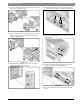
| Horizontal Configurability SM Series Heat Pump 3. Remove and retain bracket by removing (3) screws. (Figure #8) 6. Rotate the blower into its new position.(Figure#11) Figure # 8 Figure # 11 4. Loosen blower assembly by removing (4) screws. (Figure #9) 7. Remove and retain remaining bracket by removing (2) screws. (Figure #12) Figure # 9 Figure # 12 5. Remove and retain bracket by removing (2) screws. (Figure #10) 8. Remove the blower assembly by sliding it forward.
Horizontal Configurability | 9 SM Series Heat Pump 9. Remove and discard blower collar by removing (8) screws. (Figure #14) 12. Reinstall bracket removed in step (#3) using (3) screws in the same location. (Figure#17) 1 2 Figure # 14 10. Reorient the blower assembly 180 degree with blower “belly” down and slide back into the cabinet. (Figure #15) Figure # 17 13. Reinstall remaining bracket using (2) screws. (Figure#18) 1 2 Figure # 15 11.
| Horizontal Configurability SM Series Heat Pump 16. Remove and retain plastic Blower opening cover by removing (6) screws and reinstall it in the new location (Figure#20 and #21) Instructions - Right-Hand Unit (SM0**1HZ-*R*-**) 1. Remove and retain end and side panels.(Figure#22) 2 2 1 1 Figure # 22 2. Disconnect blower motor wiring and ground wire fastened to blower housing.(Figure#23) Figure # 20 3 Figure # 23 1 2 3. Remove and retain (4) screws under the blower collar.
SM Series Heat Pump Air coil is in close proximity to the blower. Air coil fins are easily damaged. Great care must be taken during this step to avoid coil damage. Shipping cardboard can be used as protection during blower removal and installation. Horizontal Configurability | 11 6. Remove and discard horizontal blower bracket by removing (3) screws. (Figure #27) 4. Slide blower assembly away from mounting bracket. (Figure #25) Figure # 27 7. Rotate the blower into its new position.
| Horizontal Configurability SM Series Heat Pump 9. Remove the blower assembly by sliding it forward. (Figure #30) 11. Reorient the blower assembly 180 degree with blower “belly” up. (Figure #32) Unit top is notched to allow blower to slide through. Figure # 32 12. Move the blower back into the cabinet. (Figure #33) Figure # 30 10. Remove and discard blower collar by removing (8) screws. (Figure #31) Figure # 33 Figure # 31 13.
Counter-Flow configurability | 13 SM Series Heat Pump 14. Secure (2) the now horizontal blower brackets to the unit base using (4) screws. (Figure#35) 3 1 2 Figure # 37 17. Reinstall all unit panels. Figure # 35 15. Reconnect blower motor wiring and ground wire. 16. Remove and retain plastic Blower opening cover by removing (6) screws and cutting/ tearing insulation at perforations around the perimeter of cover.
| Vertical Configurability SM Series Heat Pump 3 1 Figure # 38 Top Discharge (Default) 2 Figure # 39 Back Discharge Figure # 41 [1] Logo/Front Panel [2] Electrical Box [3] Default Configuration (can be ordered as either right or left hand return) Internally mounted electric heat is only available in Top Discharge configuration.
Vertical Configurability | 15 SM Series Heat Pump Required steps Possible unit configurations How to use this table: • Select desired configuration from “possible unit configurations”. • Instructions with “X” have to be performed to reconfigure the unit.
| Vertical Configurability SM Series Heat Pump Figure # 43 2. Remove and retain Condensing Section access panels (bottom panel) by removing (3) screws. (Figure #44) Figure # 45 2) A WA Y 1) UP 2) A WA Y 1) UP Figure # 44 3. Remove and retain Air Handler Panel by lifting up and out as shown in Figure #46. Remove panel about 12" away from the cabinet and unplug LCD screen wiring. (Figures #45 and#46) Figure # 46 4. Repeat steps 1–3 for all three sides.
SM Series Heat Pump Vertical Configurability | 17 Blower Re-Configuration This instruction details re-configuration of blower from UP to SIDE discharge. Reconfiguration to other side uses similar steps. 1. Remove and retain diagonal support brackets on Front and Back sides of the unit. (Figure #47) Figure # 49 4. Remove screws on both sides of the blower securing vertical blower bracket to horizontal support.(Figure#50) Figure # 47 2.
| Vertical Configurability SM Series Heat Pump 7. Remove and retain side panel blower opening cover by removing (6) phillips head screws and cutting/tearing insulation at perforations around the perimeter of cover.(Figures #53 and #54) Figure # 51 6. Remove and discard blower collar. (Figure #52) Discharge air configuration change is not possible on Heat Pumps equipped with Electric Heat Option. Figure # 53 2 1 FRONT OF THE PANEL VIEW Figure # 52 Figure # 54 8.
SM Series Heat Pump 9. Remove and retain (2) horizontal blower support brackets by removing (4) screws in each. (Figure #56) Vertical Configurability | 19 11. Remove and retain vertical brackets from blower by removing (4) screws, (2) on each side of the blower. (Figure #58) Upper bracket contains two push-in rubber bump stops. Figure # 58 12. Reinstall vertical brackets in new orientation. (Figure #59) Figure # 56 10.
| Vertical Configurability SM Series Heat Pump 14. Reinstall blower motor and inlet ring assembly by reversing Step #6. (Figure #61) Condensate Drain Connection Reconfiguration When re-configuring the unit from Left-Hand Return to Right-Hand Return it is necessary to relocate condensate drain connection from FRONT left corner post to BACK left corner post.(Figure#63) Figure # 61 15. Reconnect blower motor electrical plug and ground wire. 16. Reinstall diagonal bracket(s).
SM Series Heat Pump 3. Locate the BACK left condensate drain and remove and retain plastic plug covering the cutout. (Figure#65) Vertical Configurability | 21 8. Reinstall condensate drain plastic fitting and bushing in its new location.(Figure#67) Figure # 67 Figure # 65 4. Reinstall the removed plastic plugs in the original Condensate Drain Location. 5. Route the flexible plastic tube from FRONT left corner post to BACK left.
| Vertical Configurability SM Series Heat Pump 2. Identify a rectangular knockout and remove it. Along with insulation.(Figure#69) 2. Remove and retain the Electric Heat Element cover(s) by removing (4) screws in each.(Figure#71) Figure # 69 3. Route HRP Pump Disconnect switch wires to the new switch location. Do not route wiring over potentially hot surfaces or exposed sharp edges. Damage to wiring could result. Figure # 71 3. Disconnect high voltage wiring a the Electric Heat Elements.
SM Series Heat Pump 5. Disconnect main Electric Heat E-box plug.(FIgure#74) Vertical Configurability | 23 8. Remove and retain Blower collar cover(s). (FIgure#77) Figure # 74 6. Remove and retain Electric Heat E-box by removing (2) screws.(Figure#75) Figure # 77 9. Re-install Electric Heat Elements in the new location. Ensure High Temperature Cutouts are located on the left side. (Figure#78) Figure # 75 7. Re-install Electric Heat E-box in the new location. (Figure#76) Figure # 78 10.
| Vertical Configurability SM Series Heat Pump 12. Reconnect high voltage wiring from Electric Heat E-Box and Heating Element(s) matching wire number to terminals as shown.(Figure#80) CAUTION: take great care to ensure all wires are disconnected and none of the wires are 'snagged' on any components HT-4 HLS-4 HLS-3 HT-3 HLS-2 HT-2 HLS-1 HT-1 RED BLACK Figure # 80 13. Re-install Electric Heat Elements Cover(s). (Figure#81) Figure # 82 4.
SM Series Heat Pump Return and Discharge Duct Flanges | 25 8. Swap FRONT panel (containing LCD) to the BACK RETURN AND DISCHARGE DUCT FLANGES Reinstall All Panels Return and discharge opening duct flanges are shipped unfolded. Flanges bend lines are perforated allowing easy bending using standard sheet metal pliers or channel locks. (Figure #91) 1. Re-route the LCD wiring to the new location and reconnect LCD screen wiring. Reinstall panels.
| Pre Installation Unit Preparation SM Series Heat Pump PRE INSTALLATION UNIT PREPARATION Corner Cap Installation Instructions Each corner cap is stamped with one the following identifiers: T, T1,T2 B, B1, B2, A. 3. Remove adhesive backing and install each Corner Cap. (Figure#89 and#90) Ensure cabinet surface is clean and free of debris to ensure proper Corner Cap Adhesion. 1. Identify Letter code on each Corner Cap. (Figure#86) Figure # 86 2.
Mounting Vertical Units | 27 SM Series Heat Pump MOUNTING VERTICAL UNITS Vertical units should be mounted level on a vibration absorbing pad slightly larger than the base to minimize vibration transmission to the building structure. It is not necessary to anchor the unit to the floor. (Figure #92). On VT and CF Units Condensate Drain pan is internally sloped. There is no internal P-Trap. The Secondary drain pan prevents possible condensate overflow or water leakage damage to the ceiling.
| Duct System SM Series Heat Pump DUCT SYSTEM A supply air outlet collar and return air duct flange are provided on all units to facilitate duct connections. Supply air duct and return air duct flanges are shipped unfolded with unit. Fold the duct flange outwards along the perforated line. Refer to unit Dimensional Drawings for physical dimensions of the collar and flange. (Pg#91 through Pg#95) A flexible connector is recommended for supply and return air duct connections on metal duct systems.
Electrical | 29 SM Series Heat Pump ELECTRICAL Refer to electrical component box layout. (Figure #94) 6 5 7 4 Field wiring must comply with local and national electric codes. 12 3 8 Power to the unit must be within the operating voltage range indicated on the unit nameplate or on the performance data sheet. 2 9 1 10 Operation of unit on improper line voltage or with excessive phase imbalance will be hazardous to the unit, constitutes abuse and may void the warranty.
| Electrical SM Series Heat Pump Safety Devices and the UPM Controller 13 If the thermostat is provided with a malfunction light powered off of the hot (R) side of the transformer, then the thermostat malfunction light connection should be connected directly to the (ALR) contact on the unit’s UPM board. 11 12 1 Each unit is factory provided with a Unit Protection Module (UPM) that controls the compressor operation and monitors the safety controls that protect the unit.
Electrical | 31 SM Series Heat Pump • Evaporator freeze protection sensor, mounted after the thermal expansion device and the evaporator, monitors refrigerant temperature between the evaporator coil and thermal expansion valve. If temperature drops below or remains at freeze limit trip for 30 seconds, the controller will shut down the compressor and enter into a soft lockout condition. The default freeze limit trip is 30°F.
| Electrical • SM Series Heat Pump active. The LED will flash (three (3) times) the code associated with this alarm condition. If this alarm occurs 2 times (or 4 if Dip switch is set to 4) within an hour the UPM controller will enter into a hard lockout condition. It will constantly monitor the refrigerant temperature with the sensor mounted close to the evaporator between the thermal expansion valve and evaporator coil as shown in Figure #5.
| 33 SM Series Heat Pump ECM INTERFACE BOARD Thermostat Outputs Refer to Figure #95, item [12] for ECM interface board location. In addition to providing a connecting point for thermostat wiring, the interface board also translates thermostat inputs into control commands for the Electronic Commutated Motor (ECM) DC fan motor and provides thermostat signlas to unit’s UPM board.
| SM Series Heat Pump Do not set the ADJ DIP switch to the (-) setting when electric heaters are installed. Doing so may cause the heaters to cycle on their thermal overload switches, potentially shortening the life of the switches. Always disconnect power before changing DIP switch positions on the interface board and reset the unit afterward. Dehumidification Method Selector Dehumidification method selector (Figure #99, item [11]) is used to select between the following two methods: 1.
Options | 35 SM Series Heat Pump OPTIONS Heat pumps with hot Gas Reheat need to be connected to a humidistat along with a traditional thermostat or a combination thermostat/humidistat. Number of factory installed options are available on SM Series of Heat Pumps. The following details the purpose, function and components of each option.
| Options SM Series Heat Pump The heat exchanger is rated for use with potable water and is acceptable for use as a domestic water heating device in most building codes. The pump circulates water between the domestic hot water tank and HRP heat exchanger in the Heat Pump. The control circuit ensures that the HRP only operates when there is available heat from the compressor and when the water is within a safe temperature range of below 140 deg F.
Heat Recovery Package | 37 SM Series Heat Pump HEAT RECOVERY PACKAGE 6. Close all valves and remove the drain hose. 7. Install HR water piping. Water Tank Preparation 1. Turn off electrical or fuel supply to the water heater. 2. Attach garden hose to water tank drain connection and run other end of hose out doors or to an open drain. 3. Close cold water inlet valve to water heater tank. 4. Drain tank by opening drain valve on the bottom of the tank, then open pressure relief valve or hot water faucet.
| Heat Recovery Package SM Series Heat Pump 6. Before restoring the power or fuel supply to the water heater, adjust the temperature setting on the tank thermostat(s) to ensure maximum utilization of the heat available from the refrigeration system and conserve the most energy. On tanks with both upper and lower elements and thermostats, the lower element should be turned down to 100° F, while the upper element should be adjusted to 120° F.
Sequence of Operation | 39 SM Series Heat Pump SEQUENCE OF OPERATION Cooling Mode Energizing the “O” terminal energizes the unit reversing valve thus placing the unit into cooling mode. The fan motor starts when the “G” terminal is energized. The fan motor will take 30 seconds to ramp up to operating speed and will run at fan only rated air flow as long as there is no call for compressor or heater operation.
| Sequence of Operation SM Series Heat Pump UPM Sequence of Operation (SOO) Flow Chart Y1=1 NO YES Power/Switchs/Sensor Status Check V > 18VAC NO Lockout Can Be Set To 4 Via Dip Switch YES HPC = 1 Blink Code On Status LED Soft Lockout Record Alarm Start Counter (If Applicable) NO COUNT = 2 YES NO YES YES LPC = 1 Start Timer NO NO YES FRZ > TEMP LIM NO Start Timer TIME > 30 SEC YES CC Output = Off NO YES CON > 0 TIME > 120 SEC Blink Code On Status LED Report Alarm Fault Hard
Application Considerations | 41 SM Series Heat Pump APPLICATION CONSIDERATIONS pressure must always be maintained in the heat exchanger. This can be accomplished with either control valve or a bladder type expansion tank. When using a single water well to supply both domestic water and the heat pump care must be taken to insure that the well can provide sufficient flow for both. In well water applications a slow closing solenoid valve must be used to prevent water hammer.
| Application Considerations SM Series Heat Pump open cooling tower may also be used. It is imperative that all air be eliminated from the closed loop side of the heat exchanger to insure against fouling. In the heating mode, heat is absorbed from the water loop. A boiler can be utilized to maintain the loop at the desired temperature. Water piping exposed to extreme low ambient temperatures is subject to freezing.
Application Considerations | 43 SM Series Heat Pump Geothermal Systems Closed loop and pond applications require specialized design knowledge. No attempt at these installations should be made unless the dealer has received specialized training. Utilizing the Ground Loop Pumping Package (GLP), makes the installation easy. Anti-freeze solutions are utilized when low evaporating conditions are expected to occur. Refer to the GLP installation manuals for more specific instructions.
| System Checkout SM Series Heat Pump SYSTEM CHECKOUT UNIT START-UP After completing the installation, and before energizing the unit, the following system checks should be made: 1. Verify that the supply voltage to the heat pump is in accordance with the nameplate ratings. 2. Make sure that all electrical connections are tight and secure. 3. Check the electrical fusing and wiring for the correct size. 1. Set the thermostat to the highest setting. 2.
SM Series Heat Pump Maintenance | 45 MAINTENANCE 1. Filter changes or cleanings are required at regular intervals. The time period between filter changes will depend upon type of environment the equipment is used in. In a single family home, that is not under construction, changing or cleaning the filter every 60 days is sufficient. In other applications such as motels, where daily vacuuming produces a large amount of lint, filter changes may need to be as frequent as biweekly.
| Unit Check-Out Sheet SM Series Heat Pump UNIT CHECK-OUT SHEET Customer Data Customer Name _____________________________________________ Address ______________________________________________________ _______________________________________________________________ Phone _______________________________________________________ Date ___________________________________ Unit Number ___________________________ Unit Nameplate Data Unit Make _________________________________________ Model Number ___________
Troubleshooting | 47 SM Series Heat Pump TROUBLESHOOTING SM Series Water Source Heat Pump is equipped with a externally mounted LCD screen that displays unit errors.
| Troubleshooting SM Series Heat Pump Unit Troubleshooting Problem UNIT OFF ON HIGH PRESSURE CONTROL UNIT OFF ON LOW PRESSURE CONTROL UNIT SHORT CYCLES INSUFFICIENT COOLING OR HEATING 6 720 220 406 (2013/9) Possible Cause Checks and Correction Discharge pressure too high In “COOLING” mode: Lack of or inadequate water flow. Entering water temperature is too warm. Scaled or plugged condenser. In “HEATING” mode: Lack of or inadequate air flow.
Troubleshooting | 49 SM Series Heat Pump Compressor Ohms Model Start Winding Run Winding SM024 1.64 1.3 SM036 1.52 0.88 SM048 1.86 0.52 SM060 1.63 0.39 SM070 1.85 0.34 Tolerance +/- 7%. All resistance values must be measured with compressor at room temperature. Comfort Alert Module -Flash Codes Status LED Status LED Description Status LED Troubleshooting Information Solution YELLOW "ALERT" FLASH CODE 3 Short Cycling Compressor is running only briefly 1.
| Troubleshooting SM Series Heat Pump Comfort Alert Module -Flash Codes Status LED Status LED Description Status LED Troubleshooting Information Solution YELLOW "ALERT” FLASH CODE 6 Open Start Circuit Current only in run circuit 1. Run capacitor has failed (may not be bad, verify) 2. Open circuit in compressor start wiring or connections • Check wiring and connectors between supply and the compressor "S'" terminal 3.
Electronic Thermostat Installation | 51 SM Series Heat Pump ELECTRONIC THERMOSTAT INSTALLATION Position the thermostat subbase against the wall so that it is level and the thermostat wires protrude through the middle of the subbase. Mark the position of the subbase mounting holes and drill holes with a 3/16-inch bit. Install supplied anchors and secure base to the wall. Thermostat wire must be 8-conductor, 18-AWG wire.
| Operating Temperatures and Pressures SM Series Heat Pump OPERATING TEMPERATURES AND PRESSURES Operating Temperatures and Pressures COOLING Model Entering Water Temp.
Operating Temperatures and Pressures | 53 SM Series Heat Pump Operating Temperatures and Pressures COOLING HEATING 4.5 30° 40° 50° SM036 Part Load 60° 70° 80° 90° 100° 9.0 40° 50° SM036 Full Load 60° 70° 80° 90° 100° 266-325 5-6 15-18 77-94 272-333 3-4 16-19 4.5 117-143 189-231 14-17 18-22 86-105 279-341 6-7 17-21 9.0 112-137 178-217 8-9 19-24 90-110 286-350 4-5 18-22 4.5 126-154 221-270 14-17 18-21 105-125 293-358 7-8 20-24 9.
| Operating Temperatures and Pressures SM Series Heat Pump Operating Temperatures and Pressures COOLING HEATING 6.0 30° 40° 50° SM048 Part Load 60° 70° 80° 90° 100° 12.0 40° 50° SM048 Full Load 60° 70° 80° 90° 100° 248-303 5-6 15-18 67-82 254-311 3-4 16-19 6.0 109-134 183-224 18-22 19-23 75-91 261-319 6-8 17-21 12.0 105-128 172-210 10-12 20-25 79-96 267-327 4-5 18-23 6.0 118-144 214-261 18-22 19-23 78-90 273-334 8-10 20-24 12.
Operating Temperatures and Pressures | 55 SM Series Heat Pump Operating Temperatures and Pressures COOLING HEATING 7.0 30° 40° 50° SM060 Part Load 60° 70° 80° 90° 100° 14.0 40° 50° SM060 Full Load 60° 70° 80° 90° 100° 256-313 5-7 19-23 73-89 261-319 4-5 20-25 7.0 113-138 172-210 18-22 19-23 81-99 277-339 7-8 22-26 14.0 110-134 161-196 12-14 20-24 86-105 283-346 5-6 23-28 7.0 116-142 206-252 17-21 19-23 93-114 299-365 8-9 24-29 14.
| Operating Temperatures and Pressures SM Series Heat Pump Operating Temperatures and Pressures COOLING HEATING 9.0 30° 40° 50° SM070 Part Load 60° 70° 80° 90° 100° 18.0 40° 50° SM070 Full Load 60° 70° 80° 90° 100° 259-316 5-7 19-23 76-92 264-322 4-5 20-25 9.0 116-141 175-213 18-22 19-23 84-102 280-342 7-8 22-26 18.0 113-137 164-199 12-14 20-24 89-108 286-349 5-6 23-28 9.0 119-145 209-255 17-21 19-23 96-117 302-368 8-9 24-29 18.
Airflow Tables | 57 SM Series Heat Pump AIRFLOW TABLES Constant Torque Motor Airflow Table (SM0**-***-***-T*) Fan Rated Models Speed Airflow SM024 SM036 SM048 SM060 SM070 5 950 4 825 3 725 2 650 1 500 5 1300 4 1100 3 950 2 800 Factory setting FL PL/Fan only FL PL/Fan only ECM Const Torque Motor - X13 External Static Pressure (in of Water) 0.10 0.20 0.30 0.40 0.50 0.60 0.70 0.80 0.90 1.00 1.10 1.
| Airflow Tables SM Series Heat Pump Constant Airflow Motor Airflow Table(SM0**-***-***-A) ECM Const CFM Motor - EON Fan Rated External Static Pressure (in of Water) Models Speed Airflow Adjust Tap 0.10 0.20 0.30 0.40 0.50 0.60 0.70 0.80 0.90 1.
Water Side Pressure Drop Table | 59 SM Series Heat Pump WATER SIDE PRESSURE DROP TABLE Water Side Pressure Drop Table Heat Pump water pressure drop Additional pressure drop in hose kit* Model GPM Water PD @ 77°EWT with Water in Psi Water PD in Psi 3 0.7 0.04 4 1.2 0.04 5 1.7 0.09 SM024 6 2.4 0.09 7 3.2 0.13 8 4.0 0.17 4.5 1.3 0.09 6 2.2 0.09 7.5 3.2 0.17 SM036 9 4.5 0.22 10.5 5.9 0.30 12 7.5 0.35 6 1.1 0.09 8 1.8 0.17 10 2.7 0.26 SM048 12 3.7 0.35 14 4.9 0.48 16 6.2 0.61 7.5 1.1 0.17 10 1.9 0.26 12.5 2.
| Wiring Diagrams SM Series Heat Pump WIRING DIAGRAMS Figure # 108 6 720 220 406 (2013/9) Subject to change without prior notice SM Series Heat Pump
Wiring Diagrams | 61 SM Series Heat Pump Figure # 109 Revised 08-13 6 720 220 406 (2013/9)
| Wiring Diagrams SM Series Heat Pump Figure # 110 6 720 220 406 (2013/9) Subject to change without prior notice SM Series Heat Pump
Wiring Diagrams | 63 SM Series Heat Pump Figure # 111 Revised 08-13 6 720 220 406 (2013/9)
| Wiring Diagrams SM Series Heat Pump Figure # 112 6 720 220 406 (2013/9) Subject to change without prior notice SM Series Heat Pump
SM Series Heat Pump Revised 08-13 Wiring Diagrams | 65 6 720 220 406 (2013/9)
| Wiring Diagrams SM Series Heat Pump Figure # 113 6 720 220 406 (2013/9) Subject to change without prior notice SM Series Heat Pump
Wiring Diagrams | 67 SM Series Heat Pump Figure # 114 Revised 08-13 6 720 220 406 (2013/9)
| WIRING HARNESS DRAWINGS SM Series Heat Pump WIRING HARNESS DRAWINGS Constant Torque Motor (SM0**-***-***-T*) Figure # 115 6 720 220 406 (2013/9) Subject to change without prior notice SM Series Heat Pump
WIRING HARNESS DRAWINGS | 69 SM Series Heat Pump Constant Airflow Motor (SM0**-***-***-A*) Figure # 116 Revised 08-13 6 720 220 406 (2013/9)
| Spare Parts List SM Series Heat Pump SPARE PARTS LIST This section is divided into three parts: Vertical (VT), Counter Flow (CF) and Horizontal (HZ). Each section is started with kit names and part numbers, followed by exploded view illustration identifying all the available components, assemblies and kits.
Spare Parts List | 71 SM Series Heat Pump 39 Clip Kit 8733802680 8733802680 8733802680 8733802680 8733802680 8733802680 8733802680 8733802680 8733802680 8733802680 40 * Upper Panel Blower Kit 8733802681 8733802768 8733802768 8733802769 8733802769 8733802681 8733802768 8733802768 8733802769 8733802769 41 * Logo Panel Kit 8733802682 8733802770 8733802770 8733802771 8733802771 8733802682 8733802770 8733802770 8733802771 8733802771 42 * Lower Panel Access Kit 8733802683 8733802772 8733802772 873380
| Spare Parts List SM Series Heat Pump VT Parts List - Cabinet 6 720 220 408 (02) Figure # 117 6 720 220 406 (2013/9) Subject to change without prior notice SM Series Heat Pump
Spare Parts List | 73 SM Series Heat Pump 6 720 220 408 (02) VT Parts List - Blower Figure # 118 Revised 08-13 6 720 220 406 (2013/9)
| Spare Parts List SM Series Heat Pump VT Parts List -Refrigeration and Electrical 6 720 220 408 (02) Figure # 119 6 720 220 406 (2013/9) Subject to change without prior notice SM Series Heat Pump
Spare Parts List | 75 SM Series Heat Pump 6 720 220 408 (02) VT Parts List - Detailed Views Figure # 120 Revised 08-13 6 720 220 406 (2013/9)
| Spare Parts List SM Series Heat Pump 6 720 220 408 (02) VT Parts List - Detailed Views Figure # 121 6 720 220 406 (2013/9) Subject to change without prior notice SM Series Heat Pump
Spare Parts List | 77 SM Series Heat Pump Horizontal (HZ) HORIZONTAL CONFIGURATION - PARTS LIST Item Part / Desc SM024-1HZC SM024-1HZN SM036-1HZC SM036-1HZN SM048-1HZC SM048-1HZN SM060-1HZC SM060-1HZN SM070-1HZC SM070-1HZN 1 Floating Base Pan Kit 8733802642 8733802642 8733802642 8733802642 8733802642 8733802642 8733802642 8733802642 8733802642 8733802642 2 Water Coil Kit 8733802643 8733802719 8733802715 8733802720 8733802716 8733802721 8733802717 8733802722 8733802718 8733802723 7 Compressor Kit
| Spare Parts List SM Series Heat Pump 74 # 10kW EH Element Kit - - 8733802793 8733802793 8733802793 8733802793 8733802793 8733802793 8733802793 8733802793 75 # 10kW EH Cntrl Box KIT - - 8733802794 8733802794 8733802794 8733802794 8733802794 8733802794 8733802794 8733802794 76 # 10kW EH Contactor Kit - - 8733802795 8733802795 8733802795 8733802795 8733802795 8733802795 8733802795 8733802795 77 # 15kW EH Element Kit - - - - 8733802796 8733802796 8733802796 8733802796 8733802796 8733
Spare Parts List | 79 SM Series Heat Pump HZ Part List - Cabinet 6 720 220 429 (01) Figure # 122 Revised 08-13 6 720 220 406 (2013/9)
| Spare Parts List SM Series Heat Pump 6 720 220 429 (01) HZ Parts List - Blower Figure # 123 6 720 220 406 (2013/9) Subject to change without prior notice SM Series Heat Pump
Spare Parts List | 81 SM Series Heat Pump HZ Parts List - Refrigeration 6 720 220 429 (01) Figure # 124 Revised 08-13 6 720 220 406 (2013/9)
| Spare Parts List SM Series Heat Pump 6 720 220 429 (01) HZ Part List - Panels Figure # 125 6 720 220 406 (2013/9) Subject to change without prior notice SM Series Heat Pump
Spare Parts List | 83 SM Series Heat Pump 6 720 220 429 (01) HZ Part List - Detailed View Figure # 126 Revised 08-13 6 720 220 406 (2013/9)
| Spare Parts List SM Series Heat Pump Counter Flow Part List COUNTER FLOW CONFIGURATION - PARTS LIST Item 1 2 6 7 8 9 10 11 13 14 15 16 17 18 19 20 21 22 # 23 24 * 25 # 26 # 27 # 28 29 # # 30 # 31 # 32 # 33 # 34 # 35 # Part / Desc SM024-1CFC SM024-1CFN SM036-1CFC SM036-1CFN SM048-1CFC SM048-1CFN SM060-1CFC SM060-1CFN SM070-1CFC SM070-1CFN Floating Base Pan Kit 8733802642 8733802642 8733802642 8733802642 8733802642 8733802642 8733802642 8733802642 8733802642 8733802642 Water
Spare Parts List | 85 SM Series Heat Pump 60 # 62 63 64 65 66 67 68 69 # 70 # 71 # 72 73 # 74 # 75 76 77 # # # 78 # 79 # 80 # 81 82 83 # # # HRP Water Temp Sensor Kit 8733802702 8733802702 8733802702 8733802702 8733802788 8733802788 8733802788 8733802788 8733802788 8733802788 HRP Pump Kit 8733802703 8733802703 8733802703 8733802703 8733802703 8733802703 8733802703 8733802703 8733802703 8733802703 HGRH Coil Kit 8733802704 8733802704 8733802789 8733802789 8733802789 8733802789 873
| Spare Parts List SM Series Heat Pump 6 720 220 430 (00) Counter Flow Part List - Cabinet Figure # 127 6 720 220 406 (2013/9) Subject to change without prior notice SM Series Heat Pump
Spare Parts List | 87 SM Series Heat Pump 6 720 220 430 (00) Counter Flow Part List - Blower Figure # 128 Revised 08-13 6 720 220 406 (2013/9)
| Spare Parts List SM Series Heat Pump 6 720 220 430 (00) Counter Flow Part List - Panels Figure # 129 6 720 220 406 (2013/9) Subject to change without prior notice SM Series Heat Pump
Spare Parts List | 89 SM Series Heat Pump 6 720 220 430 (00) Counter Flow Part List - Refrigeration Figure # 130 Revised 08-13 6 720 220 406 (2013/9)
| Spare Parts List SM Series Heat Pump 6 720 220 430 (00) Counter Flow Part List - Detailed View Figure # 131 6 720 220 406 (2013/9) Subject to change without prior notice SM Series Heat Pump
Dimensional Drawings | 91 SM Series Heat Pump DIMENSIONAL DRAWINGS Figure # 132 Revised 08-13 6 720 220 406 (2013/9)
| Dimensional Drawings SM Series Heat Pump Horizontal - Straight Through Figure # 133 6 720 220 406 (2013/9) Subject to change without prior notice SM Series Heat Pump
Dimensional Drawings | 93 SM Series Heat Pump Horizontal - Hanging bracket location Figure # 134 Revised 08-13 6 720 220 406 (2013/9)
| Dimensional Drawings SM Series Heat Pump Counter Flow Figure # 135 6 720 220 406 (2013/9) Subject to change without prior notice SM Series Heat Pump
Dimensional Drawings | 95 SM Series Heat Pump Vertical Figure # 136 Revised 08-13 6 720 220 406 (2013/9)
| Notes SM Series Heat Pump NOTES 6 720 220 406 (2013/9) Subject to change without prior notice SM Series Heat Pump
SM Series Heat Pump Revised 08-13 Notes | 97 6 720 220 406 (2013/9)
| Notes 6 720 220 406 (2013/9) SM Series Heat Pump Subject to change without prior notice SM Series Heat Pump
SM Series Heat Pump Revised 08-13 Notes | 99 6 720 220 406 (2013/9)
601 N.W. 65th Court, Ft. Lauderdale, FL 33309 Phone: 866-642-3198 | Fax: 954-776-5529 www.boschtaxcredit.com | www.bosch-climate.