Solution 16 plus ���������������� EN Quick Start Guide Security System
Solution 16plus Quick Start Guide Co py r i ght Notice Te l e p e r m i t N o te Unless otherwise indicated, this publication is the copyright of Bosch Security Systems Pty Ltd (“Bosch”). All rights are reserved.You may download a single copy of this publication.
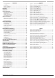
Solution 16plus Quick Start Guide CONTENTS Copyright Notice .................................................................................. 2 Trademarks ............................................................................................. 2 Notice of Liability.................................................................................. 2 Telepermit Note .................................................................................... 2 FEATURES ...........................................
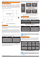
Solution 16plus Quick Start Guide Fe at u re s O ve r v i e w Listed below are the main features of the Solution 16plus Control Panel. Zones The Solution 16plus control panel provides up to 16 separate zones of protection. Zone programming determines the panel’s response to open/short and tamper conditions on the zone loop.
Solution 16plus Quick Start Guide Ab o u t The Panel M o u nting The Cabinet 257 The cabinet should be mounted via 4 (screws/bolts) through the 4 mounting holes in the base. Ensure that the enclosure is mounted on a solid, flat, vertical surface such that the base will not flex when tightened. Cabinet dimensions are shown below.
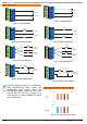
Solution 16plus Quick Start Guide Wi r i n g Diagrams ���� ���� ��� ZONE 2 N/C ���� ZONE 1 N/O ZONE 2 ��� ZONE 1 N/C N/O 2 ���� Figure 7: N/O No EOL Zone Figure 3: N/C No EOL Zone ALARM N/C ��� N/C ZONE 2 ��� N/C ALARM ���� ZONE 1 ALARM (3K3 EOL) ���� ZONE 9 (6K8 EOL) (6K8 EOL) ZONE 1 ZONE 9 Figure 9: N/O Split EOL Zone TAMPER (6K8 EOL) N/C ZONE 1 (3K3 EOL) ����2 ���� ��� N/C TAMPER TAMPER (6K8 EOL) ALARM TAMPER ALARM ���� N/C (3K3 EOL) N/O ���
Solution 16plus Quick Start Guide ��������� ������������ ������������� �������������� ���������� ��������� ��������� ������������ ������������ �������� ��������� ����� ��������� ������������� ����������� ����������� �������������������� ����������� ������ �������������������� ���������������������� ������������ ����������������� ���������� ������������ ������ ������������� ������������ ��������������� ���������� ��������������� ������ ������������ ��������� ������������ ����������� ������������ ����
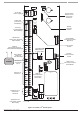
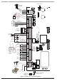
Solution 16plus Quick Start Guide Connect To Cabinet Tamper 16Vac 22VA Plug Pack GREEN YELLOW YELLOW + 12VDC 7Ah Sealed Lead Acid Battery - + Accessories (e.g.
Solution 16plus Quick Start Guide Te r m i nal Descriptions Nº Name 1 Earth 2 3 ~ (AC) ~ (AC) Connection of the A.C. plug pack transformer 4 5 BAT (-) BAT (+) Negative and positive connections to the stand-by battery. 12 VDC / 7AH 6 7 8 9 10 11 +12 V +12 V +12 V GND GND GND These terminals are used to power detectors and LAN devices up to 750 mA. 12 13 LAN + LAN - These terminals are used to power LAN devices up to 750 mA. LAN A Connect the LAN A data terminal of any LAN device (eg.
Solution 16plus Quick Start Guide Key Description The [ON] key allows you to turn an area or output on. To turn all areas on at the same time when the system has been partitioned, press and hold the [ON] key for two seconds. The [PART] key allows you to turn an area Part On. This key can also be used to bypass a zone or multiple zones when you press and hold for two seconds. The [OFF] key allows you to turn an area or output off.
Solution 16plus Quick Start Guide St at u s Icons / LED ’s The following table lists the function of each of the ICON Symbols and LED Indicators on the Graphic Keypad Display. Icon Status Meaning The keypad can display which areas (1 – 8) are turned on or off via the Area Icon Indicators.
Solution 16plus Quick Start Guide Pro gra mming O ver view The Solution 16plus Control System incorporates a menu text driven interface. This interface is very similar to that found on many mobile phones. Once programming mode is entered you will see a number of menu options in the display and these may vary depending in the user authority level. E nte r i n g Programming M ode “Move To An Area” or “Turn An Area On”. Use the up and down arrow keys to navigate and press [OK] to select the command.
Solution 16plus Quick Start Guide [MENU] to exit without saving. G e t t i n g St a r te d B a c k To B a s e The following additional special characters are available by scrolling using the up and down arrow Note keys. + - @ # $ “ & % * : ( ) / < > = i Te l e p hone Numb ers To program, select primary telephone number under [MENU] 5-1-1 then enter the digits of the telephone number and press the [OK] key to save. Use the up and down arrow keys to program special characters (, # and Pause).
Solution 16plus Quick Start Guide To Hardware Default 1) Remove All Power To The System. AC and Battery. 2) Press and Hold The Default Push Button Down Then Apply Power To The System. 3) Release Button, The Panel Will Reset And Revert To Normal Operation When Default Is Complete. Zo n e Ar ray The feature allows you to view the condition of 16 zones at a time on a single display. From the installer programing mode press [Menu] 3-0-1 to access the zone array.
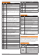
Solution 16plus Quick Start Guide M e n u Reference Table The Solution Controller includes a simple text menu system which makes all levels of programming extremely easy. Once a valid PIN has been entered followed by the MENU key the system will automatically determine which menus and option the user has access to and only those items will be displayed.
Solution 16plus Quick Start Guide 3 Inputs AMI I UMI MI MI UMI 3-0 3-0-0 3-0-1 3-0-2 3-0-3 3-0-4 3-0-5 Commands Zone Status Zone Array Bypass Zones Set Chime Zones Set Part 2 Zones Smoke Sensor Reset MI I I I I I I I I 3-1 3-1-0 3-1-1 3-1-2 3-1-3 3-1-4 3-1-5 3-1-6 3-1-7 3-1-8 Zone Properties Zone Name Zone Type Area Assignment Pulse Count Pulse Count Time Access Group Report Route Report Options Zone Options I I I 3-3 3-3-0 3-3-1 3-3-2 RF Zone Add RF Device Delete RF Device Test RF Device I I I
Solution 16plus Quick Start Guide 6 UMI I Devices 6-0 Commands 6-0-0 LAN Status 6-0-1 LAN Secure 7 System UMI UMI UMI I I I I 7-0 7-0-0 7-0-1 7-0-2 7-0-3 7-0-4 7-0-5 7-0-8 Commands Panel Status System Trouble History Log Domestic Default Factory Default Template Default Service Mode MI I I 7-1 7-1-0 7-1-1 7-1-2 Clock Set Date & Time Summertime On Summertime Off MI MI MI I I I I I I 6-1 6-1-0 6-1-1 6-1-2 6-1-3 6-1-4 6-1-5 6-1-6 6-1-7 6-1-8 Keypads Volume Contrast Backlight Home Area General Opti
Solution 16plus Quick Start Guide Pro gra m Locations Access > User Properties > The following section lists all of the programming locations available in the Solution 16plus. The default values for each parameter are shown in grey. In order to keep the size of this guide down to a minimum we have shown only one example for some parameters and then listed the default values for the other similar parameters. For example the User Default Table below shows the default values for Users 1 to 48.
Solution 16plus Quick Start Guide Access > Prox Reader > Access > Global Properties > MENU 1-5-0 PIN Length 4 0 = Variable MENU 1-6-3 1 All On Arming Allowed Y 4 = 4 Digits 7 = 7 Digits 2 Disarming Allowed Y 2 = 2 Digits 5 = 5 Digits 8 = 8 Digits 3 Badging Required N 3 = 3 Digits 6 = 6 Digits 4 Zero Exit Time N 5 Part On Badging Allowed N 6 Arm If Single Area User N 7 Reserved N 8 Reserved N 1 = 1 Digit Enter 0 - 15 + [OK] To Program The PIN Length Option.
Solution 16plus Quick Start Guide Areas > Reporting > Areas > Properties > Input Options MENU 2-1-2 0 1 Non Sequential Handover (Entry Path) Y 2 Pulse Count Handover Allowed Y 3 Senior Watch N 4 Reset Smoke On Arming Y Areas > Reporting > 5 Reserved N 6 Account Dest 2 Reserved N 7 Reserved N 8 Reserved N Use Keys [] and [] to scroll up and down the option list. With option selected press ON / OFF key to enable or disable option. [] will display to indicate option set.
Solution 16plus Quick Start Guide I n p u t Programmi ng Inputs > Zone Properties > Inputs > Commands > Pulse Count Time Zone Status MENU 3-0-0 Zone Array MENU 3-0-1 Bypass Zones MENU 3-0-2 Set Chime Zones MENU 3-0-3 Set Part 2 Zones MENU 3-0-4 Smoke Sensor Reset MENU 3-0-5 Inputs > Zone Properties > MENU 3-1-0 Zone Name Z o n e 1 N a m e 1 Inputs > Zone Properties > MENU 3-1-1 1 Use Keys [] and [] keys or enter 0 – 15 + [OK] To Program Zone Type Zone Types 0 Enter 0 – 255 +
Solution 16plus Quick Start Guide Zo n e D efault Table The table below list the default values for all zone parameters in the Solution 16plus. By default, zones 5 to 16 are set as Instant zones. Zones marked as Not Used do not require EOL resistors to be fitted.
Solution 16plus Quick Start Guide O u t p u t Pro gra m m i n g Inputs > Tamper Inputs > Tamper Options Outputs > Commands > MENU 3-6-0 1 Display Panel Tamper Y 2 Report Panel Tamper Y 3 Audible Panel Tamper Y 4 Display Expander Tamper Y 5 Report Expander Tamper Y 6 Audible Expander Tamper Y 7 Reserved N 8 Reserved N Use Keys [] and [] to scroll up and down the option list. With option selected press ON / OFF key to enable or disable option.
Solution 16plus Quick Start Guide O u t p u t Event Types 0 = Disabled 1 = Battery Trouble 2 = AC Trouble 3 = Telephone Line Trouble 4 = Comm Fail – Destination 1 / 2 5 = Third Dialler Attempt 6 = Destination 1 Reporting 7 = Destination 2 Reporting 8 = Destination 1 or 2 Kiss Off 9 = Destination 1 Kiss Off 10 = Destination 2 Kiss Off 11 = Dialler Disabled 12 = Horn Speaker Missing 13 = Output Trouble 14 = Panel On Line 15 = Incoming Call 16 = System Trouble 17 = Box Tamper 18 = Zone Trouble 19 = Zone Mirror 2
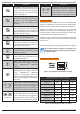
Solution 16plus Quick Start Guide Comms > Telephone Number > Outputs > Properties > Output Options MENU 4-1-5 MENU 5-1-1 Primary Dest 1 1 Digits 1 Do Not Operate On Low Battery Y 2 Display Overload Y 3 Report Overload Y 4 Display Device Fail Y 5 Report Device Fail Y 6 Alarm On Device Fail N Comms > Telephone Number > 7 Block If Armed All On N Secondary Dest 1 8 Display Output Status On Keypad N Use Keys [] and [] to scroll up and down the option list.
Solution 16plus Quick Start Guide Comms > Telephone Number > Call Forward Off 1 # Digits 6 1 Comms > Properties > MENU 5-1-7 32 p # Use [] and [] Keys To Scroll Cursor. Enter [0] – [9] For Telephone Digits. Use [] and [] To Toggle Special Characters # and , (Pause) Comms > Properties > MENU 5-2-0 Call Attempt Count 0 s s w d Comms > Remote Access > MENU 5-3-0 Call Back Number 1 Digits 32 Use [] and [] Keys To Scroll Cursor. Enter [0] – [9] For Telephone Digits.
Solution 16plus Quick Start Guide Comms > Remote Access > Comms > Dialler Reporting > DTMF Options MENU 5-3-5 MENU 5-4-1 TX Format Dest 2 1 DTMF Arming Y 0 = Disable 2 DTMF Disarming N 1 = Contact ID 7 = Domestic 3 DTMF User Functions N 2 = SIA 8 = Voice 13 = Reserved 9 = SIA + 14 = Reserved 15 = Reserved 1 4 DTMF Quick Arm ([0] + [#]) Y 3 = Serial STU 5 Reserved N 4 = GSM 10 = Reserved 11 = Reserved 12 = Reserved 6 Reserved N 5 = WEB MAIL 7 Reserved N 6 = SMS 8 Res
Solution 16plus Quick Start Guide Comms > Comms Test > Comms > Dialler Reporting > MENU 5-4-6 Burg Report Delay 0 0 1 = Report Events To Destination 1 + Log SECONDS 2 = Report Events To Destination 2 + Log Enter 0 – 255 seconds + [OK] To Program The Delay Time In Seconds Before Reports Are Sent. 0 = No Delay (*** System Wide Parameter ***) MENU 5-4-7 Fire Report Delay 0 0 Enter 0 – 255 seconds + [OK] To Program The Delay Time In Seconds Before Reports Are Sent.
Solution 16plus Quick Start Guide Devices > Keypads > Beeper Options Device > RF Devices > MENU 6-1-5 MENU 6-2-1 Supervision Time 1 Trouble Alert Beeps Y 2 Entry Warning Y HOURS 3 Exit Warning Y 4 Chime Tone Y Enter the RF Supervision Time for Devices in Hours (001 - 255 Hours) 000 = No Supervision 5 Display Temperature N 6 PIN Arming Not Allowed N 7 Intaller PIN Not Allowed N 8 Show Alarm When Armed N Use Keys [] and [] to scroll up and down the option list.
Solution 16plus Quick Start Guide Sys te m Programming System > Timers > System > Commands > MENU 7-2-3 Part Entry Time Panel Status MENU 7-0-0 System Trouble MENU 7-0-1 History Log MENU 7-0-2 Domestic Default MENU 7-0-3 System > Timers > Factory Default MENU 7-0-4 Auto Arm Pre-Alert Template Default MENU 7-0-5 Service Mode MENU 7-0-8 0 6 0 SECONDS (*** System Wide Parameter ***) Enter 0 - 255 + [OK] To Program The Part Mode Entry Time In Seconds.
Solution 16plus Quick Start Guide System > Power > System > Schedules > Battery Options MENU 7-3-1 MENU 7-5-1 Time 1 Display Battery Fail Y 2 Report Battery Fail Y 12 3 Execute Battery Testing On Arming Y HH 4 Arming Allowed On Low Battery Y 5 Reserved N 6 Reserved N 7 Reserved N 8 Reserved N Use Keys [] and [] to scroll up and down the option list. With option selected press ON / OFF key to enable or disable option. [] will display to indicate option set.
Solution 16plus Quick Start Guide System > Installer Options > System > System Options > General Options MENU 7-7-0 Installer Options MENU 7-7-4 1 Display LAN Fail Y 1 Report/Log Entry/Exit Intstaller Menu 2 Report LAN Fail Y 2 Report/Log Program Data Change Y 3 Alarm On LAN Fail N 3 Arm Only Installer Pin N 4 Reserved N 4 Reserved N 5 Can Change Own PIN Code N 5 Auto Exit Installer Menu In 2 Hours Y 6 Monitor Default PIN Codes Y 6 Auto Exit Service mode In 2 Hours Y
Solution 16plus Quick Start Guide Communication Test Use MENU 5-9-0 to test the telephone reporting capability of the control panel. You can also activate a communication test by holding down the Test / Mail key on the keypad.
Solution 16plus Quick Start Guide NOTES: 34 Bosch Security Systems 09/06 BLCC100R
Solution 16plus Quick Start Guide INSTALLATION DETAILS CUSTOMER NAME: PHONE: INSTALLED BY: DATE: ACCOUNT N°: PANEL LOCATION: PANEL PHONE N°: CLI ENABLED: N° WIRED ZONES: N° OF USERS: N° RF ZONES: N° OF AREAS: WARRANTY EXPIRES: COMMON AREA USED: USER TRAINING DONE: PERSON TRAINED: NOTES: Bosch Security Systems 09/06 BLCC100R 35
Bosch Security Systems 25 Huntingwood Drive Huntingwood, NSW 2128 Australia Phone: +612 9672 1777 Facsimile: +612 9672 1717 © 2006 Bosch Security Systems BLCC100R 920656 Issue FTR1.