Solution-16 Operators Manual ISSUE 1.
!"#$%&"'()*+ Operators Manual Copyright 2002 by Electronics Design and Manufacturing Pty Limited, SYDNEY, AUSTRALIA Document Part Number MA880O DOCUMENT ISSUE 1.60 Printed 22 March 2002 This documentation is provided to suit the !"#$%&"'()*,!"#$%&"'()*+!-./0"1 Control Panel (CC880/LP880/SC8016). Firmware Revision 1.10 – 2.06 Hardware Revision A - K Alarm Link required = 2.74 or higher Copyright Notice All rights reserved.
Table Of Contents INTRODUCTION .................................................................................................................................. 6 CODEPAD INDICATORS.................................................................................................................... 7 Zone Indicators ..................................................................................................................................................... 7 AWAY Indicator.............................
Telephone Line Fail....................................................................................................................................... 17 E2 Fault.......................................................................................................................................................... 17 Zone 16 In Alarm - Partitioned Systems Only .............................................................................................. 18 Communication Fail ...........................
BASIC PAGER REPORTING ........................................................................................................... 29 Basic Pager Display Information....................................................................................................................... 29 Subscriber ID Number................................................................................................................................... 29 Zone Status ..........................................................
!"#$%&"'()* Operators Manual Introduction Congratulations on selecting the !"#$%&"'()* control panel to protect you and your property. So that you can obtain the most from your unit, we suggest that you take the time to read through this manual and familiarise yourself with the numerous outstanding operating features of this system. You will notice that in all aspects of planning, engineering, styling, operation, convenience and adaptability, we have sought to anticipate your every possible requirement.
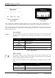
!"#$%&"'()* Operators Manual 7 Codepad Indicators Figure 1: CP5 Eight Zone LED Codepad Figure 2: CP5 Eight Zone LCD Codepad The codepad is the communications interface between you and your alarm system. The codepad allows you to issue commands and offers both visual and audible indications that guide you through the general operation. The codepad incorporates numerous indicators. There are zone indicators that are used to show the condition of each zone and four others for general status.
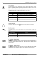
!"#$%&"'()* Operators Manual STAY Indicator The STAY indicator is used to display that the system is armed in STAY Mode 1 or STAY Mode 2. The STAY indicator will also flash in unison with the AWAY indicator when programming various options throughout the operator’s manual. Refer to page 11 for information on the different methods of arming in STAY Mode 1. For information and the method of arming in STAY Mode 2, refer to page 12.
!"#$%&"'()* Operators Manual 9 FAULT Indicator The FAULT indicator is used to display that the system has detected a system fault. Refer to Fault Analysis Mode on page 16 for additional information on system faults. Every time a new system fault has been detected (eg. FAULT indicator flashing), the codepad will begin to beep once every minute. Pressing the # button once will cancel the once a minute beep and acknowledge the fault (eg. FAULT indicator on steady).
!"#$%&"'()* Operators Manual Arming The System There are several different ways to arm the system depending on whether you are leaving the premises and require all active zones to be in a ready state for an intruder, or, if you are remaining in the premises and only require part of the system to be in a ready state for an intruder. If a zone is not sealed at the end of exit time, the zone will be automatically isolated and will be constantly displayed on the codepad.
!"#$%&"'()* Operators Manual 11 Arming In STAY Mode 1 STAY Mode 1 is only used when the perimeter and unused areas of the premises need to be armed to detect any would be intruder from entering the premises and at the same time, allowing you to move freely within an area that has been automatically isolated. Only your security company can program zones to be automatically isolated in STAY Mode 1. There are two different methods for arming the system in STAY Mode 1.
!"#$%&"'()* Operators Manual 12 Arming In STAY Mode 2 STAY Mode 2 is only used when the perimeter and unused areas of the premises need to be armed to detect any would be intruder from entering the premises and at the same time, allowing you to move freely within an area that has been automatically isolated. Any Master Code holder can program programming zones to be automatically isolated in STAY Mode 2.
!"#$%&"'()* Operators Manual 13 Disarming The System When you enter the premises after the system has been armed in AWAY Mode, or if you have armed the system in STAY Mode 1 or STAY Mode 2, you will need to disarm the system to disable detection devices that will activate an alarm. If there has been an alarm condition prior to disarming the system, a flashing zone indicator will be displayed, indicating a previous alarm on that zone. How To Disarm The System 1.
!"#$%&"'()* Operators Manual Codepad Duress Alarm A codepad duress alarm is used as a silent hold-up alarm. This will only occur when the number 9 is added to the end of any valid user code that us being used to disarm the system (eg. 2580 + 9#). A duress alarm is only useful if your system is reporting back to a monitoring station or pocket pager as domestic reporting (ie. mobile phone etc) can’t decipher which type of alarm had occurred.
!"#$%&"'()* Operators Manual 15 Isolating Zones Isolating zones allow you to manually disable one or more zones before arming the system. Once a zone has been isolated, access is allowed into that zone during the armed state without activating an alarm. An example when you may require to isolate a zone before arming the system could be when a PIR detector may be false alarming or that you may need to leave a pet inside a particular zone whilst you are away.
!"#$%&"'()* Operators Manual 16 Code To Isolate The method will restrict only those user codes that have the priority level ‘Code To Isolate’ set to be able to isolate zones. Therefore, if any user code has this priority level set, the method of standard isolating will not function. Your security company can only program the priority level for each user code. How To Isolate A Zone 1. Press the * button followed by your user code and the * button again to enter the isolating mode (eg. *2580*).
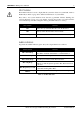
!"#$%&"'()* Operators Manual 17 Zone Indicator 1 2 3 4 5 6 7 8 Description Battery Fail Date & Time Sensor Watch Horn Speaker Fail Telephone Line Fail E2 Fault Zone 16 In Alarm (Partitioned Systems Only) Communication Fail Table 7: Fault Indicators Fault Descriptions Low Battery A low battery fault will register when the system detects a low capacity back-up battery. The system automatically performs a battery test every 4 hours and also every time you arm the system.
!"#$%&"'()* Operators Manual 18 Zone 16 In Alarm - Partitioned Systems Only This fault will register when Zone 16 has registered an alarm condition. The AUX indicator will display if a ‘Master Partitioned’ codepad is used if the system has been partitioned. You may need to contact your installer regarding this fault. Communication Fail A communication fail will register when the control panel failed to communicate with the receiving party (eg. monitoring company, mobile phone or pocket pager etc).
!"#$%&"'()* Operators Manual 19 Turning Output Devices On/Off This feature is only applicable if your security company has programmed an output that can operate external devices (ie. toggle on/off via the codepad). The output programmed by your security company could control a pool pump or outside lighting etc. Up to five different outputs can be programmed. How To Turn An Output On or Off 1. Enter your Master Code followed by 5 and the # button (eg. 2580 + 5 + #).
!"#$%&"'()* Operators Manual 20 Testing There are various functions that allow you to test that your system is operating correctly. Horn Speaker Test 1. Press and hold button 1 until two beeps are heard. The horn speaker will sound for two seconds. Bell Test 1. Press and hold button 2 until two beeps are heard. The bell output will operate for two seconds. Strobe Test 1. Press and hold button 3 until three beeps are heard. The strobe will now flash. 2.
!"#$%&"'()* Operators Manual 21 Day Alarm Day alarm allows a combination of zones to be monitored during the disarmed state by beeping the codepad buzzer. Only your installer can program zones 1 – 4 to operate for day alarm. Example An example set-up of a day alarm could be the front door of a shop that has a pressure mat or electronic beam that customers activate as they enter to and from the shop. As the customers walk onto the pressure mat or break the electronic beam, the codepad buzzer will beep.
!"#$%&"'()* Operators Manual 22 Partitioning Your control panel can be partitioned or split into four individual areas. Each areas can be operated from one ‘Master Partitioned’ codepad, or from separate ‘Area Addressable’ codepads. Master Partitioned Codepad Indicators The indicators on a ‘Master Partitioned’ codepad are configured into four groups (ie. Zone Indicators, Area On/Off Display, Area Display and Status Indicators). Refer to Figure 5: Master Partitioned Codepad.
!"#$%&"'()* Operators Manual 23 Operation Of Codepads In Partitioning Area Addressable Codepad Operations If you have a system that has been partitioned with ‘Area Addressable’ eight zone codepads, the operating procedure is exactly the same as described as a non-partitioned system except that all operations are only relative to the area that the codepad has been assigned to.
!"#$%&"'()* Operators Manual Remote Arming Via Telephone This feature allows you to arm your system from any remote location via the telephone. For obvious security reasons, the system cannot be disarmed using this method. To make use of this feature, you will require a touch-tone telephone and a phone controller. Your security company needs to program this feature to operate. How To Remotely Arm Your System Via The Telephone 1. Call the telephone number that your control panel is connected to. 2.
!"#$%&"'()* Operators Manual 25 Operating The System Via A Touch-Tone Telephone If the system has been installed with an optional DTMF command module, the system can be operated via a touch-tone telephone. Once a communication link has been established between a touch-tone telephone and your alarm system, you can operate the system via the telephone as if you where operating the system at a codepad. How To Establish A Communication Link 1. 2. Dial the telephone number that the system is connected to.
!"#$%&"'()* Operators Manual 26 Domestic Dialling Domestic dialling can be used to call your mobile phone or a relative/friend in the event that your control panel has activated an alarm. Up to three different telephone numbers may be programmed for the control panel to call when alarm occurs. Only your installer can program the system to report in the domestic format, however, the Master Code holder may change the telephone numbers at any time.
!"#$%&"'()* Operators Manual 27 Programming Domestic Telephone Numbers If your system has been set-up for domestic dialling, this function allows any Master Code holder to program telephone numbers that the control panel will call in the event of an alarm. How To Program Telephone Numbers 1. Enter your Master Code followed by 2 and the # button (eg. 2580 + 2 + #). Three beeps will be heard and the STAY and AWAY indicators will begin to flash.
!"#$%&"'()* Operators Manual 28 Domestic Voice Message Reporting The system can be configured by your security company to report to your mobile phone when an alarm occurs and playback a pre-recorded message detailing instructions. The pre-recorded message can be changed as many times as necessary (up to a maximum of 16 seconds in length). You will need to discuss the recording of your message with your security company.
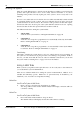
!"#$%&"'()* Operators Manual 29 Basic Pager Reporting This feature is only applicable if your system is reporting to a pocket pager. Basic pager reporting requires some interpretation of the numbers that appear of the display. However, it is possible to differentiate between 1000 different systems when a number of control panels are reporting to the one pocket pager.
!"#$%&"'()* Operators Manual Figure 6: Basic Pager Display The example above shows that the transmission has come from the control panel that has an ID number of 678 and that zone 2 is in alarm. The example also displays that zone 3 has been manually isolated and the system is armed. ISSUE160.
!"#$%&"'()* Operators Manual 31 PET Pager/SMS Reporting The system can be configured by your security company to report to your mobile phone via SMS messaging or a pocket pager when an alarm and/or any system event occurs. When using either of these two reporting formats, easy to understand text messages will be received so that the appropriate action can be taken. The following table list all the events that can be reported in SMS messaging and PET pager formats.
!"#$%&"'()* Operators Manual 32 Glossary Of Terms Term Description Alarm Condition Is when your alarm system is armed and one of the detection devices have been violated. A 24-hour zone (eg. smoke detector) can activate an alarm condition when your system is armed or disarmed.
!"#$%&"'()* Operators Manual 33 Term Description Hand Held Remote Control Can be used to remotely operate your system via hand held transmitters (Also known as RF keyfobs). Isolating Allows you to manually disable (isolate) one or more zones before arming the system. Master Code Is a numerical code used for arming and disarming the system as well as allowing access to functions such as adding and deleting user codes etc.
!"#$%&"'()* Operators Manual 34 Term Description User Code A user code is the personal identification number that the operator uses to arm and disarm the system. Zones 24-Hour Zones ISSUE160.DOC A monitored input used to trigger an alarm condition when violated. A monitored input programmed to trigger an alarm condition when violated when the system is armed or disarmed 24-hours a day.
!"#$%&"'()* Operators Manual 35 Warranty Statement Electronics Design and Manufacturing Pty Limited warrants this product to be free from defects in material and workmanship for a period of three years from the date of manufacture as indicated by the date stamp and / or serial number on the product. Defective units returned by the purchaser at their own expense during this period will be repaired or replaced at the option of the manufacturer.
!"#$%&"'()* Operators Manual 36 Advice To Users The Austel permit that has been issued for this product is subject to the following conditions: • The Solution-16 control panel may only be powered by an EDM TF008 plug pack (Approval Number Q92128). New Zealand Telepermit Notes • The grant of a telepermit for a device in no way indicates Telecom acceptance of responsibility for the correct operation of that device under all operating conditions.
!"#$%&"'()* Operators Manual 37 Installation Notes Installation Company Technicians Name Technicians Telephone Number Installation Date Warranty Expires Panel Software Version Service Notes Electronics Design and Manufacturing Pty Limited ISSUE160.
!"#$%&"'()* Operators Manual 38 Zone Descriptions This allows you to describe each zone and tick which zones have been programmed to be automatically isolated in STAY Mode 1 or have been programmed for day alarm operation. Isolated In STAY Day Alarm Mode 1 Zone 1 Zone 2 Zone 3 Zone 4 Zone 5 Zone 6 Zone 7 Zone 8 Zone 9 Zone 10 Zone 11 Zone 12 Zone 13 Zone 14 Zone 15 Zone 16 ISSUE160.
!"#$%&"'()* Operators Manual 39 User Code Names Master Code Default = 2580 User #1 Y Master Code User #17 User #2 User #18 User #3 User #19 User #4 User #20 User #5 User #21 User #6 User #22 User #7 User #23 User #8 User #24 User #9 User #25 User #10 User #26 User #11 User #27 User #12 User #28 User #13 User #29 User #14 User #30 User #15 User #31 User #16 User #32 Auxiliary #1 Auxiliary #2 (User #33) (User #34) Electronics Design and Manufacturing Pty Limited ISSUE16
!"#$%&"'()* Operators Manual 40 Entry / Exit Times Entry Time 1 Exit Time Entry Time 2 Entry Guard Time Entry Time 3 Entry Time 4 Arming Options Single Button Arming (AWAY/STAY) YES NO Forced Arming YES NO Single Button Disarming (STAY Mode) YES NO Remote Arming Via Telephone YES NO Automatic Arm In AWAY Mode YES NO Automatic Arm In STAY Mode YES NO Automatic Arming Warning Time Minutes Automatic Arming Time AM/PM Automatic Disarming Time AM/PM Output Descriptions ISSUE160.
!"#$%&"'()* Operators Manual 41 Isolating Method Standard Isolating Code To Isolate YES NO YES NO Back To Base Reporting YES NO Panel Account Number Domestic Reporting YES NO Domestic Reporting – No Of Beeps Basic Pager Reporting YES NO PET Pager/SMS Reporting YES NO Remote Arming Allowed YES NO DTMF Command Module Fitted YES NO Communication Options Other System Information Siren Run Time Minutes Sensor Watch Time Can Your System Be Serviced Days YES NO If Yes, Installer’
!"#$%&"'()* Operators Manual Index 2 24-Hour Zones.............................................................. 34 E A Access Denied .............................................................. 14 Adding User Codes....................................................... 13 Advice To Users ........................................................... 36 Alarm Condition ........................................................... 32 Answering Machine Bypass .........................................
!"#$%&"'()* Operators Manual N New Zealand Telepermit Notes.....................................36 O Off Indicator....................................................................8 On Indicator ....................................................................8 Output Devices - Turn On/Off ......................................19 Outputs Reset Latching Outputs.............................................19 P Pager Reporting.............................................................29 Panic Alarm ...