
Installation and Operating Guide

Electrical connections
Greentherm T9900 SE/i – 6 720 813 635 (2022/01)
44
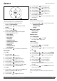
4.13 Measuring gas pressure
4.13.1 Gas supply pressure
Confirm gas pressure upon installation.
Connecting manometer
▶ Shut off gas supply at installer supplied shutoff valve for
this water heater.
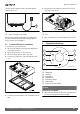
▶ Locate the inlet gas pressure test port (see Fig. 35).
▶ Loosen the screw inside test port fitting (do not remove)
and connect the manometer tube to the test port (see
Fig. 35).
Static Pressure Test
▶ Turn the gas supply back on.
▶ Record the static gas pressure reading in table 21.
Dynamic Pressure Test
▶ Turn ON the appliance.
▶ Access menu P1 Max. Power, see section 6.6.
Note: While in this mode the appliance will run constantly at
maximum power and allow maximum water flow.
For inlet gas pressure adjustment consider the following table:
Table 20 Minimum inlet gas pressure under full operation
▶ Operate all other gas appliances (except heater) on the
same gas piping system at maximum output.
▶ Open all hot water faucets to achieve a flow rate of at least
6 gallons per minute. (1 tub and 2 sinks should be
sufficient). If heater goes back to P2, open more hot water
fixtures to allow sufficient flow to keep the water heater in
P1.
▶ Record the lowest operating gas pressure reading in
table 21.
▶ Turn OFF the appliance.
▶ Shut off gas supply.
▶ Disconnect the manometer tube from the test point.
▶ Tighten the screw inside test point fitting.
Depending on the vent length, gas pressures below 5" W.C. for
Natural Gas or 8" W.C. for LPG may result in reduced power
output or possible error codes and must be corrected. See Gas
Connections, chapter 4.8, page 33.
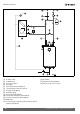
Fig. 35 Gas pressure test port
[1] Gas pressure measuring port
Table 21 Inlet gas pressure readings
5 Electrical connections
5.1 Electrical power supply
DANGER:
Risk of electric shock!
▶ For safety reasons, disconnect the power supply cord to
the water heater before any service or testing is performed.
DANGER:
▶ This water heater must be electrically grounded in
accordance with the most recent edition of the National
Electrical Code. NFPA 70. In Canada, all electrical wiring to
the heater must be in accordance with local codes and the
Canadian Electrical Code, CSA C22.1 Part 1. Do not rely on
the gas or water piping to ground the metal parts of the
heater.
WARNING:
▶ Modification of or tampering with the power supply cord is
prohibited.
▶ Use of extension cords is prohibited.
The water heater requires an electrical power supply from a
120VAC / 60Hz properly rated receptacle and must be properly
grounded.
Gas type NG LPG
Inlet gas Pressure 3.5” WC
1)
1) To assure maximum heat input at maximum vent length, the
minimum gas pressure should be 5" W.C. for the 199 kBTU
models and 4" W.C. for the 160 kBTU models. For more
information see section 4.6.3.
8” WC
Gas pressure Date
Static Gas Pressure Reading
Dynamic Gas Pressure
Reading