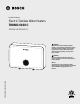
Installation Manual Electric Tankless Water Heaters TRONIC 6100 C TR6100C-18 | TR6100C-27 WARNING: This manual must only be used by a qualified installer / service technician. Read all instructions in this manual before installing. Perform steps in the given order. Failure to do so could result in substantial property damage, severe personal injury, or death. WARNING: Improper installation, adjustment, alteration, service or maintenance can cause injury, death, or property damage.
Installation Manual 2| Bosch Tronic 6100 C Electric Tankless Water Heaters - BTC 724001301 C (03.
Installation Manual Table of Contents 1 Key to Symbols and Safety Instructions 4 1.1 Key to Symbols 1.2 Safety 4 4 2 Prepare the Water Heater 6 2.1 2.2 2.3 2.4 6 6 6 7 7 8 8 lnspect Shipment Water Heater Rating Label Location Clearances Locating the Water Heater 2.4.1 Installation Area (Mechanical Room) Operating Conditions 2.4.2 Centralized Location 2.4.
Installation Manual 1 Key to Symbols and Safety Instructions WARNING: IMPORTANT SAFETY INSTRUCTIONS 1.1 Key to Symbols f When using electrical appliances, basic safety precautions to reduce the risk of fire, electric shock, or injury to persons should be followed, including: Warnings Warnings in this document are identified by a warning triangle printed against a grey background.
Installation Manual WARNING: IMPROPER OR DANGEROUS OPERATION f If the water heater is exposed to the following, do not operate. Immediately call a qualified service technician. — Fire — Damage WARNING: HAZARDOUS VOLTAGE f When Servicing the Water Heating System be sure to disconnect electrical power before performing service. Failure to do so could result in electrical shock, property damage, serious personal injury, or death.
Installation Manual 2 Prepare the Water Heater Water Temperature Adjustment The water heater thermostat has been pre-set at the factory at a temperature equal to 125°F (52°C). Follow local codes and if the water heater is going to have a set temperature above 120°F, install an ASSE 1017 rated mixing valve to avoid severe burns or death from scalding temperatures. After adjusting the water temperature at the thermostat, allow the water heater enough time to heat the water to temperature.
Installation Manual 2.4.1 Installation Area (Mechanical Room) Operating Conditions NOTICE: PRODUCT DAMAGE f High heat sources (sources generating heat 100°F / 37°C or greater, such as stove pipes, space heaters, etc.) may damage plastic components of the water heater. Such damages ARE NOT covered by warranty. It is recommended to keep a minimum clearance of 8” from high heat sources.
Installation Manual 3 Water Quality Requirements 2.4.2 Centralized Location Choose a location for the water heater as centralized to the piping and electrical system as possible. Also, locate the water heater and domestic water piping where it will not be exposed to freezing temperatures. All piping should be insulated. Additionally, place the water heater so that the drain, controls, and inlets/outlets are easily accessible.
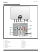
Installation Manual 4 Water Heater Components 7 6 3 2 1 4 5 8 10 12 9 13 14 16 15 15 11 Figure 2 Water Heater Components 1 Power Button 9 2 Digital Temperature Display 10 Heating Canister 3 Temperature Setting Buttons 11 Heating Element 4 LED Indicator 12 High Limit Switch 5 Cold Water Intlet 13 Terminal Block 6 Hot Water Outlet 14 Ground Connection 7 Electrical Knockout/Strain Relief 15 Thermistor 8 Inlet Water Filter 16 Flow Switch Triac Bosch Tronic 6100 C Electr
Installation Manual 5 Dimensions 13 1/4" 6 3/8" 8 1/2" 20 1/4" Figure 3 10 | 6 1/16" 5 1/8" Dimensions Bosch Tronic 6100 C Electric Tankless Water Heaters - BTC 724001301 C (03.
Installation Manual 6 Technical Specifications TR6100C-18 TR6100C-27 240V 18 27 208V 13.5 20 240V 75 112.5 208V 65 96 Required Breaker(s) 208V/240V 3 x 30A Double Pole 3 x 40A Double Pole Required Wire Size 208V/240V 3 x 10 AWG w/Ground 3 x 8 AWG w/Ground Description Wattage (kW)* Max Amperage Minimum Water Flow to Activate 0.5 gpm Working Pressure 7 - 150 psi (0.
Installation Manual 7 Installation 7.1 Wall Mounting the Water Heater 2 2 1. Remove the 2 screws used for shipping on the backside of the unit and recycle. They are no longer needed. 2 1 Figure 6 4. Disconnect wiring harness connected to the inside of the front cover. Figure 4 2. Remove 2 screws located on the bottom of the cover and save for reinstallation.
Installation Manual 7. The appliance must be mounted upright, with water inlets and outlets at the bottom. See Figure 8. WARNING: IMPROPER OPERATION, PERSONAL INJURY, PRODUCT DAMAGE f This water heater must be installed upright in the vertical position as described in this manual. DO NOT attempt to install this water heater in any other orientation. Doing so will result in improper water heater operation and property damage, and could result in serious personal injury or death.
Installation Manual 7.2 Plumbing It is mandatory that all plumbing be done in accordance with federal, local, and state plumbing codes and practices. Failure to properly install the water heater WILL VOID the warranty. It is also best practice to use thread tape on all mechanical plumbing connections. f Minimum pipe size should match water heater connection. f The installer is responsible for all equipment and components required by local codes.
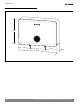
Installation Manual 7.3 Installation Example This drawing is meant to demonstrate system piping only. CHECK VALVE BALL VALVE AUTOMATIC WATER SHUT-OFF VALVE COLD WATER INLET UNION HOT WATER OUTLET WATER LEAK DETECTION SENSOR DRAIN PRESSURE RELIEF VALVE (IF REQUIRED BY LOCAL CODE) Figure 10 Bosch Tronic 6100 C Electric Tankless Water Heaters- BTC 724001301 C (03.
Installation Manual 7.5 Scalding WARNING: SCALD HAZARD f An ASSE 1017 or ASSE 1070 temperature limiting or mixing valve is recommended in installations servicing disabled or elderly persons, or children. Mixing valves do not eliminate the risk of scalding. To avoid scalding: — Set the water heater set point temperature as low as possible. — Feel water before bathing or showering. — If thermostatic valves are required, use devices specifically designed for such purpose.
Installation Manual 7.7 Electrical Connection DANGER: HAZARDOUS VOLTAGE f Failure to disconnect the power from the water heater before attempting to install or repair it will result in property damage, severe personal injury, or death. WARNING: PERSONAL INJURY, PROPERTY DAMAGE f All wiring (wire gauge) as well as circuit protection (breakers) must comply with the National Electrical Code (NEC) in the USA and done by a qualified licensed electrician or the local electric utility.
Installation Manual 7.8 Wiring Diagrams 7.8.1 Power Supply Wiring for 18 and 27kW Grounding Block in Unit Terminal Block in Unit L1 L2 L1 L1 L2 L1 L2 L2 240V L1 240V L2 240V L1 L2 Unit requires 10 AWG for 18kW, 8 AWG for 27kW wire with ground - one for each 240 V circuit. Figure 11 Voltage phasing is important. The voltage between each L1 should be less than 5V.
Installation Manual 7.8.2 Internal Wiring Diagram for 18kW PE(G) Bottom Plate L1 L2 THERMOSTAT 1 Auto 60 THERMOSTAT 2 Auto 60 THERMOSTAT 3 Auto 60 G TRIAC 2 G TRIAC 1 H.E 3 H.E 2 H.E 1 HEATER DISPLAY G TRIAC 3 PCBA CNTRL1 -HEATER CONTROL UNIT | 19 Bosch Tronic 6100 C Electric Tankless Water Heaters- BTC 724001301 C (03.2024) L1 L2 L1 L2 SEN1- FLOW SENSOR SEN2- IN TEMP. SENSOR SEN3- OUT TEMP.
Installation Manual 7.8.3 Internal Wiring Diagram for 27kW L1 L2 L1 L2 L1 THERMOSTAT 4 Manual 85 THERMOSTAT 5 Manual 85 SEN1- FLOW SENSOR SEN2- IN TEMP. SENSOR SEN3- OUT TEMP. SENSOR THERMOSTAT 1 Auto 60 THERMOSTAT 2 Auto 60 THERMOSTAT 3 Auto 60 G TRIAC 1 G TRIAC 2 G TRIAC 3 PCBA CNTRL1 -HEATER CONTROL UNIT H.E 1 H.E 2 H.E 3 HEATER DISPLAY Bosch Tronic 6100 C Electric Tankless Water Heaters - BTC 724001301 C (03.
Installation Manual 8 Installation Checklist Water Heater Location Yes No Yes No Yes No Yes No Close to area of heated water demand? Indoors and protected from freezing temperatures? Area free of flammable vapors / combustibles? Provisions made to protect area from water damage? Sufficient room to service heater? Relief Valve (If required by local, state, or provincial codes) Temperature and Pressure Relief Valve properly installed and discharge line run to open drain? Discharge line protected fr
Installation Manual 9 Operation Setting the Outlet Water Temperature This tankless electric water heater is designed to supply hot water instantaneously on demand. The unit contains heating elements capable of heating water quickly for as long as necessary. f Press the Unlike a conventional tank storage water heater, this tankless water heater does not store hot water.
Installation Manual 11 Maintenance WARNING: PERSONAL INJURY, PROPERTY DAMAGE 11.1 Removing the Cover 1. Remove 2 screws located on the bottom of the cover and save for reinstallation. f Do not attempt to repair this water heater yourself. Call a qualified service technician for assistance. Always turn off the power supply to the heater prior to servicing or draining the heater. Failure to do so could result in property damage, severe personal injury, or death.
Installation Manual 3. Disconnect wiring harness connected to the inside of the front cover. 11.2 Cleaning the Inlet Pre-Filter 1. Remove and clean the pre-filter on the inlet water side once every year and any time maintenance is performed on the heater. 2. Wash lightly to remove any debris. 3. Reinstall filter and purge air from the system prior to turning on power. Figure 18 WARNING: ELECTRICAL HAZARD Figure 17 4. Remove cover completely.
Installation Manual 11.4 Removing a Heating Element 1. Shut off the power supply and drain the water heater. 2. Remove the front cover per the instructions in Section 11.1 or damage may occur. 5. In order to remove the heating element, you must unlock it from the tab on the inside of the heating canister. Push the element bottom up slightly into the canister and then rotate to release it from the heating canister tab. See Figures 22 & 23. 3. Remove all 6 wires connected to the heating element.
Installation Manual 6. Pull down to emove the heating element. Figure 26 9. Align tab on the inside of the heating canister with notch in element bottom so they are slightly off center. Push the element bottom up slightly into the canister so it is above heating canister tab. Then rotate to align notch with the tab. Pull element down to seat notch in the heating canister tab. Figure 24 7. Install new element with red O-Ring, making sure the O-Ring and element are positioned correctly.
Installation Manual 10. Reinstall element containing cap on the water heating canister to secure the element. 11.5 Descaling the Heating Element Scale deposits can affect the heating capability of the element. Heavy scale can even cause damage to the element. NOTICE: PRODUCT DAMAGE f Failure of electric elements due to lime scale build-up on the heating surface, low pH, or other imbalance IS NOT covered by the warranty. See Section 3. The element can be descaled either chemically or manually.
Installation Manual 12 Troubleshooting Before calling for service check the troubleshooting list of common issues. This can save time and cost. If you are unable to resolve a problem contact your installer or Customer Service for support (Phone: 1-866-642-3198). Alternatively, please visit our Service & Support webpage to find FAQs, videos, service bulletins, and more; www.boschheatingcooling.com/service or use your cellphone to scan the code below.
Installation Manual Troubleshooting continued Problem Possible Causes Solution Water Temperature Varies from Hot to Cold During Use Water pressure has dropped below minimum level Increase the flow rate from the water supply source Water flow is not stable or it is varying Ensure stable water flow, check for plumbing issues/crossovers Not enough water flowing through the heater Increase the flow rate at the water outlet.
Installation Manual 12.1 High Limit Switches 12.2 Checking Thermostat Operation To check thermostat operation: WARNING: ELECTRICAL HAZARD f Failure to disconnect the power from the water heater before attempting to install or repair it will result in property damage, severe personal injury, or death. Occasionally, the high temperature limit switches may trip, resulting in power being shut down as a safety precaution. This can happen if the water temperature exceeds 135°F/57°C.
Installation Manual 12.3 Testing the Heating Element To Test Heating Element: 1. Verify that circuit breakers are off and there is no voltage at the unit. 2. Disconnect wires from the heating element. It is recommended to mark or take a picture of wire positions for reinstallation. 3. Using a 200 ohm range on a digital multi-meter, measure resistance (ohms) across the wire connections on the base of each heating element canister.
Installation Manual 12.4 Testing / Changing a Triac To Test Triac: A failed triac might cause overheating or irregular heating or no heating at all. If all other troubleshooting steps mentioned above do not reveal the problem, follow below instructions to test the triacs. 1.
Installation Manual 3. Remove the two (2) screws holding the triac to the inlet pipe. Remove the triac. 4. Install the new triac to the inlet pipe using the two (2) screws. 5. Re-attach the wiring to the triac 6. Re-attach internal protective cover and front cover. 7. Return heater to service. If further assistance is needed, our technical support team is available Monday to Friday via: Email: www.boschheatingcooling.
Installation Manual NOTES: 34 | Bosch Tronic 6100 C Electric Tankless Water Heaters - BTC 724001301 C (03.
Installation Manual NOTES: Bosch Tronic 6100 C Electric Tankless Water Heaters- BTC 724001301 C (03.
United States Bosch Thermotechnology Corp. 65 Grove St. Watertown, MA 02472 Tel: 866-642-3198 www.bosch-homecomfort.us BTC 722103301 B | 105523 C | 03.2024 Bosch Thermotechnology Corp. reserves the right to make changes without notice due to continuing engineering and technological advances.