Thermostat Installation and Operation Manual Series Bosch Communicating Thermostats TSTBT4H2CP Series TSTBT4H2CP-M--A TSTBT4H2CPHM--A 6 720 220 387 Revised 06-13
TSTBT4H2CP SERIES Table of Contents The TSTBT4H2CP Series offers:.................................... 3 Lost Gateway Communication.................................... 28 Thermostat Application Guide...................................... 3 Low Heating Output.................................................... 28 TSTBT4H2CP Series Thermostat Quick Reference....... 4 Low Cooling Output.................................................... 28 Features of the Transmitting and Receiving Module (TRM)......
TsTbT4h2Cp seRies Thermostat application guide The Bosch TSTBT4H2CP Thermostat Series consists of 4-wire MODBUS communicating thermostats. Utilizing RS485 MODBUS protocol, the TSTBT4H2CP Thermostat Series can communicate with the equipment, monitor the performance, and report the status of the equipment. The MODBUS protocol is received and then translated to pulses to be received by the HVAC equipment. This translation is performed by the TRM (Transmitting and Receiving Module).
TsTbT4h2Cp seRies quick Reference TsTbT4h2Cp seRies TheRMosTaT quiCK RefeRenCe getting to know your thermostat Displays the operating mode, Schedule, Temporary Hold mode, or Hold. Displays the operating Schedule, Temporary Hold or Hold. Displays the schedule period, Morning, Daytime, Evening period, or Night. Displays the schedule Morning, Daytime, Evening or Night. Displays time of day and weekday Displays time of day and weekday Day Day Displays heating, cooling or RH setpoint.
TSTBT4H2CP SERIES Transmitting and Receiving Module 5 Features of the Transmitting and Receiving Module (TRM) Mercury Notice: All Bosch thermostats are mercury free. However, if the product you are replacing contains mercury, dispose of it properly. Your local waste management authority can give you instructions on recycling.
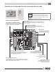
n n 6 TsTbT4h2Cp seRies installing the Thermostat insTalling The TsTbT4h2Cp TheRMosTaT seRies Caution A trained, experienced technician must install this product. Carefully read these instructions. You could damage this product or cause a hazardous condition if you fail to follow these instructions. See the product specifications at the end of this manual prior to installing. To insure a solid fit between the thermostat and the subbase: 1. Mount subbase to a flat wall 2. Use screws provided 3.
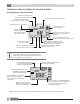
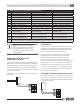
Wiring the Thermostat TsTbT4h2Cp seRies The other LED is labeled HVAC. This light indicates if the unit is actively heating or cooling. If the unit is cooling, Caution then the LED is yellow, if the unit is in heating, then the LED is red. If the thermostat is satisfied, then the LED if off. WiRing The TheRMosTaT and ReCeiving Module The thermostat is wired to the Receiving module using 4-conductor, 18–22 gage thermostat wire. Wire the thermostat and Receiving modules as shown below.
TSTBT4H2CP SERIES Wiring Diagrams Wiring Diagrams UNIT WITH ACTIVE OR PASSIVE DEHUMIDIFICATION AND HUMIDIFICATION R C O B HEAT PUMP EQUIPMENT W1 W2 H Y1 PASSIVE / ACTIVE DEHUMIDIFICATION Y2 G DH HUMIDIFIER EQUIPMENT HUM HUM HUMIDIFIER SOLENOID ALR OUT COM ALR COMMON FROM HVAC EQUIPMENT ALARM CONTACT ON FHP/BOSCH EQUIPMENT * HUMIDIFICATION AND DEHUMIDIFICATION FEATURES ARE ONLY AVAILABLE WITH TSTBT4H2CPHM--A 6 720 220 387 Subject to change without prior notice Revised 06-13
Temperature sensor Connections TsTbT4h2Cp seRies 9 Terminal Designations on the TSTBT4H2CP Thermostat Series 3 Heat / 2 Cool Conventional System 3 Heat / 2 Cool Heat Pump System 4 Heat / 2 Cool Heat Pump System C 24 Volt Common 24 Volt Common 24 Volt Common R 24 Volt Power 24 Volt Power 24 Volt Power O Energized in Cooling Energize Reversing Valve in Cooling Energize Reversing Valve in Cooling B Energized in Heating Energize Reversing Valve in Heating Energize Reversing Valve in Heating
TSTBT4H2CP SERIES Temperature Sensor Connections TS1 Used as Leaving Air Temperature Sensor A sensor can be installed in the supply duel to monitor the Leaving air temperature for monitoring equipment performance. The stainless steel tube should inserted in the duct down stream from the plenum. When both TS 1 and TS2 are used as remote space temperature sensors, both sensor readings will be averaged with the thermostat sensor reading.
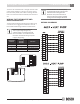
Remove the Battery Tab TSTBT4H2CP SERIES Tech Setup Features 11 • The blank button is a CANCEL button. Push this button to exit the menu setup and discard the last change made. The blank button can be pressed at any time during the setup process to exit. Navigating Through Setup Menu To access the installer menu, press and hold the ENTER button for 4 seconds until the first feature appears.
Option Number TSTBT4H2CP SERIES Option Title Tech Setup Menu Option Description LCD will Show Selects whether second stage is latched on once it is called. Use the Up and Down keys to select On or Off. Press the MENU key to go to the next option. Option 6 Second Stage Latching Range: On or Off MENU Factory Default Settings Adjustment Options NEXT ENTER Select for On or OFF for Off. Range: 0 to 9 minutes.
Tech Setup Menu Option Number Option Title TSTBT4H2CP SERIES Option Description LCD will Show 13 Range: Not used, Outdoor, leaving air or remote space temperature sensor. Select TS1 is outdoor temperature sensor. Select sensor. TS1 is discharge air temperature Option MENU NEXT 14 Not Used ENTER Select TS1 is remote temperature sensor. Internal thermostat sensor and remote sensor are averaged.
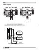
TSTBT4H2CP SERIES Tech Setup Menu 64F 65F Time must be equal to or greater than 2 minutes. 66F Time must be equal to or greater than Heating UpStage Time (Option28) 67F Heat3 Time must be equal to or greater than Heating UpStage Time (Option28) Heat2 68F Heat1 69F Heat4 Time must be equal to or greater than Heating UpStage Time (Option28) Staging response (Option09) Time must be equal to or greater than Minimum Off Time (Option05) 70F Time Figure 1.
Tech Setup Menu Option Number Option Title TSTBT4H2CP SERIES Option Description LCD will Show Adjustment Options 15 Factory Default Settings Option MENU 21 Range: Off, de-humidify using cooling or de-humidfy De-Humidification using hot gas. Control Over Cooling Range: 2 to 5F, 1 to 3C NEXT ENTER Message HEA T SYSTEM AUT O MENU MODE NEXT ENTER FAN De-humidification will only occur after a cooling call.
Option Number TSTBT4H2CP SERIES Option Title Tech Setup Menu Option Description LCD will Show Adjustment Options Factory Default Settings This option is skipped if the thermostat is wired to a Receiving Module. If the thermostat is used with a zoning panel, use the Up and Down keys to select the Zone number. Press the MENU key to go to the next option. 1 Zone Option 27 Range: 1 to 7.
Tech Menu setup explanations TsTbT4h2Cp seRies 17 TeCh Menu seTup eXplanaTions Option Option Description Adjustment Option 1: This feature establishes the temperature scale to be used and (°F or °C). 1. Push or to select the desired temperature scale that is displayed in the upper right hand corner. This feature establishes the type of equipment that you want to control. 1. Push neXT to select the appropriate equipment type. Temperature Scale option 2: equipment Type 2.
TsTbT4h2Cp seRies Tech Menu setup explanations Option Option Description Adjustment option 7: This feature establishes the minimum allowable run time for the compressor. The minimum run time prevents short run time and lengthens the life of the compressor. The compressor will continue to run for the specified number of minutes even if the set point has been satisfied. 1. Push or to select the minimum number of minutes that the compressor will run.
Tech Menu setup explanations TsTbT4h2Cp seRies 19 Option Option Description Adjustment option 11: This feature establishes the minimum space temperature that will be allowed. If the space temperature falls below the established value, the thermostat will bring on the equipment in heating mode; even if the thermostat’s operation mode is set to “OFF”. The normal heating cycle as determined by all the User Setup Features will be followed (this includes the staging sequence, min run time, min off time).
TsTbT4h2Cp seRies Tech Menu setup explanations Option Option Description Adjustment option 15: This feature enables the use of a humidifier. The TRM has a dedicated set of dry contacts in order to connect the humidifier. The setup technician must set the humidity set point to establish the desired humidity level that should be maintained. 1. Push neXT to enable the humidifier function by choosing “ON” or disabling the humidifier function by choosing “OFF”.
Tech Menu setup explanations TsTbT4h2Cp seRies 21 Option Option Description Adjustment option 20: This feature helps to establish if the cooling equipment is not functioning properly. The thermostat does this by comparing the set point temp to the space temperature and the amount of time that has passed from when the cooling call was initiated. If 30 minutes has passed and the space temperature is 30 °F or more from the set point temperature, then there might be a problem with the cooling equipment.
TsTbT4h2Cp seRies Tech Menu setup explanations Option Option Description Adjustment option 23: This feature allows the ability to delay the fan motor from energizing for a specified amount of time while in the heating mode. This is especially helpful on Gas systems; this will allow the burners to get up to temperature before air starts circulating. 1. Push neXT to enable by selecting “ON” or disable this feature by selecting “OFF”.
Tech Menu setup explanations TsTbT4h2Cp seRies 23 Option Option Description Adjustment option 29: This feature allows the thermostat to determine how quick it needs to command the next stage of cooling based upon the temperature differential. The unit will up stage according to the the minimum time as set in this option and the staging response differential as set in option 9.
TSTBT4H2CP SERIES Tech Menu Setup Explanations TSTBT4H2CP Thermostat Series Options Settings Option Option Description Factory Setting (Default) Where Option is configured when connected to: TRM Bosch Zone Panel Degrees F Thermostat Zone Panel Conventional HP (CHP) Thermostat Zone Panel 1 Degrees C or F 2 Equipment Type 3 Number of Compressors 1 Thermostat Zone Panel 4 Number of Auxiliary Heating 2 Thermostat Zone Panel 5 Outdoor Temp for Fossil Fuel Off Thermostat Zone Pa
Understanding Swing And Staging TSTBT4H2CP SERIES 24 Fan on during Daytime Schedule Days Fan On during Daytime Schedule Off Thermostat Zone Panel 25 Thermostat Key Lockout Lockout Combination Off Thermostat Zone Panel 26 Thermostat Key Lockout Lockout Combination Off Thermostat Thermostat 27 Zone Number 1 Thermostat Thermostat 28 Heating Upstage Time 5 Minutes Thermostat Thermostat 29 Cooling Upstage Time 5 Minutes Thermostat Thermostat 30 Filter Monitor Filter Replacement H
TsTbT4h2Cp seRies service Messages displaying and ReseTTing The seRviCe Messages displaying equipMenT seRviCe Messages The“Filter”,“HumPad”or“UV Bulb”will blink whenever their service hours have exceeded the time interval in 100s of hours for cleaning or replacement. After servicing the filter, humidifier pad or UV bulb, press and hold the key area in gray for 4 seconds to reset the hours. The word“Message”will blink anytime an equipment service message is present.
freeze Condition alert Message TsTbT4h2Cp seRies Message HEAT HEAT SYSTEM SYSTEM AUTO AUTO MENU 27 MODE NEXT ENTER FAN MENU MODE NEXT ENTER FAN bRoWnouT aleRT Message HEAT SYSTEM AUTO MENU MODE NEXT ENTER The equipment has detected a power brownout condition and prohibited heating and cooling calls. Contact yourlocal contractor for service. Press the enTeR key to return to normal thermostat display.
TSTBT4H2CP SERIES 28 Lost Equipment Communication Lost Equipment Communication The thermostat has detected a loss of communication with the equipment,receiving module or zoning panel. Check the wiring connections. See the troubleshooting section at the end of this manual or contact your local contractor for service. Press the ENTER key to return to normal thermostat display. .
Initial Thermostat Settings Initial Thermostat Settings The user options can be accessed using Menu key or by pressing certain areas on the LCD. TSTBT4H2CP SERIES Day Schedul e We AM Heat Set To Inside Selecting Heating or Cooling By pressing SYSTEM button, you can rotate through the 4 operation mode choices: OFF, HEAT, EmHEAT, COOL, AUTO. Select OFF to turn both heating and cooling off. Select HEAT for heating only or COOL for cooling only. Select AUTO for automatic changeover of heating and cooling.
TsTbT4h2Cp seRies setting the Time and day of the Week Permanent Hold mode is a permanent temperature override and ignores the schedule and maintains the settings established by the and keys until the status is manually changed by the user. Press here to change time of day .
7 Day Program Schedule period has two set points, one for Cooling Mode and one for Heating Mode. 1. From the thermostat home screen, press MENU twice or “Schedule” to enter the Programming Setup Menu. 2. MORN is the first time period displayed. 3. Use the or button to adjust the start time for the current time period. The time duration is in 15 minute intervals. 4. Push Next. 5. Set the set point for the Heating mode using the or button.
TsTbT4h2Cp seRies locking the Thermostat 22. Continue in this fashion to remove “Wed”, “Thu”, & “Fri’ from the days being displayed. 3. The Cancel key (blank key-second from the left) can be pushed at any time to cancel out of the sequence and will return to the home screen without changes saved. 23. At this point, only “Sat” & “Sun” should be displayed. Caution Press enTeR button.
Calibrating the Indoor Temperature Sensor TSTBT4H2CP SERIES Calibrating the Indoor Relative Humidity Sensor (Applicable for TSTBT4H2CPHM--A, & TSTBT4H2CPHMW-A models only) The indoor relative humidity sensor can be calibrated to match any reference. By pressing the MENU button 4 times from the thermostat home screen, the display below appears Use the and keys to select the indoor temperature that corresponds to your old thermostat or reference and then press ENTER.
TSTBT4H2CP SERIES 7 Day Factory Default Program 7 Day Factory Default Program Day of the Week Weekday Saturday Sunday Time Setpoint Events Time Temperature (Heat) Setpoint Temperature (Cool) Morn 6 a.m. 70° F (21° C) 78° F (26° C) Day 8 a.m. 62° F (17° C) 85° F (29° C) Eve 6 p.m. 70° F (21° C) 78° F (26° C) Night 10 p.m. 62° F (17° C) 82° F (28° C) Morn 6 a.m. 70° F (21° C) 78° F (26° C) Day 8 a.m. 62° F (17° C) 85° F (29° C) Eve 6 p.m.
Troubleshooting TSTBT4H2CP SERIES 35 TSTBT4H2CP Thermostat Series Installation Troubleshooting Problem 1 Display on thermostat not illuminated Possible Explanation Power is not available to the thermostat Possible Solution 1. V erify that 8 VDC is at the ""+VDC"" terminal. Check for proper wire connections to the thermostat mounting plate and also at the terminal connection at the TRM located by the equipment. 2. I f all connections are correct, thermostat is bad.
11 TSTBT4H2CP SERIES Troubleshooting Problem Possible Explanation A fault code is being displayed on the thermostat screen Consult a licensed professional if any of the following Reference the Fault Code faults occur: HP1, HP2, LP1, LP2, FrA, CLA, bOA, EFA, section in this manual to LEC, LHO, LCO indentify the fault Consult the literature for the gateway for fault code LGC in order to re-establish communication with the gateway Loss of Equipment Communication / No Communication 13 14 15 16 Eq
Troubleshooting TSTBT4H2CP SERIES Problem Possible Explanation Heat Pump is in cooling mode when thermostat is in heating mode or vise a versa "O" terminal is being used when the "B" terminal should be or vise a versa 18 The thermostat setpoint is not satisfied, yet there is no heating or cooling call to the equipment Remote room temperature sensors are connected and average the space temperatures with the thermostat 19 Menus described in Missing menu does not the Tech Menu Setup apply to the equi
TSTBT4H2CP SERIES Product Limited Warranty unsatisfactory performance caused by improper installation, repair or maintenance. Contact your local Bosch Dealer or Installing Contractor for product support. 6. Any labor or material costs for removal, reinstallation, repair and replacement of the defective component or part. 7. Electricity or fuel costs, or any increases or unrealized savings in same, for any reason whatsoever. 8.
product limited Warranty 4. Failure or malfunction due to misapplication or faulty building design or construction, including inadequate refrigerant levels, condensate drain, duct work design or installation. 5. Product on which payment to FHP is or has been in default. 6. Work performed without prior authorization or approval and without authorization/requisition number and without proper documentation verifying compliance with above terms.
601 N.W. 65th Court, Ft. Lauderdale, FL 33309 Phone: 866-642-3198 | Fax: 954-776-5529 www.bosch-climate.