
Instruction manual


KBE and KBN Series Installation | en 23
Bosch Security Systems, Inc. Instruction Manual F01U078718 | 2.0 | 2008.01
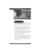
Figure 4.7 Power Wire Connection
5. Pass the supplied orange string through the mounting foot
of the camera housing and the furnished mount. See
Figure 4.2. A fitting may be used in the mounting foot if
desired.
6. Attach the end of the string to the Cat5/Cat6 cable and
pull it through the mount and the unused hole in the
mounting foot of the camera housing. See Figure 4.3.
7. Connect the Cat5 / Cat6 cable to the network connector
on the back of the camera. See Figure 4.4.
8. If an unterminated Cat5/Cat6 cable is being used, a fitting
may be used in the mounting foot of the camera housing.
The network cable should be terminated with an RJ-45
connector in accordance with the connector
manufacturer’s recommendations.
9. Seal the hole in the mounting foot of the camera housing
with RTV or an equivalent seal. See Figure 4.5. If a fitting
was used in the mounting foot, apply the seal around the
network cable before tightening the fitting, to prevent
slippage. A split rubber sleeve (not supplied) may be used
for this purpose.
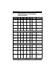
Reference Description
1Power terminal