
Installation manual

22 en | Troubleshooting UMS Series Public View System
F01U029703 | 1.0 | 2006.07 Installation Manual Bosch Security Systems, Inc.
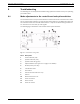
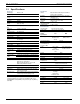
The following figure illustrates the option switches and their default settings:
Fig. 9.2 Option Switch Details
To verify the operation of the control board and to make any necessary adjustments to the
option switches, follow these steps:
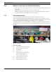
1. Manually unscrew the two (2) thumbscrews on the back of the unit. The control board
LED’s are located on the control board to the left of the camera. See Figure 9.1 on page
21, numbers 1-3.
– Verify that the Camera On LED is red when the camera input is selected and Off
when the auxiliary input is selected.
– Verify that the System Pulse LED is red, signifying that the control board is run-
ning.
– Verify that the System Power LED is green, signifying that the UMS is ON.
2. Verify the four (4) Option Switches are set to the default settings (see Figure 9.2 on page
22 for details on the respective functions).
9.2 Screen flickers
The most likely cause of a flickering screen is a power supply problem. Ensure that there is
proper AC voltage to the monitor. Running wires long distances from the power supply may
cause undesirable voltage loss. For running power longer distances, it is recommended that
you use a heavier wire gauge. Refer to a copper wire table and line loss table for exact engi-
neering specifications.
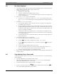
Below is a table of maximum distances that the specified wire gauges can traverse with a 24 V
transformer:
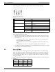
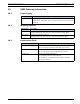
#
Control Default Setting Function
1
Motion Switcher ON Enables motion switcher
OFF Disables motion switcher
2
Not Used ON Not used
OFF Not used
3 Synchronization Mode ON Sync to Aux video
OFF Sync to line
4
Light Sensor ON Enables light sensor
OFF Disables light sensor
Gauge Distance Gauge Distance
20 AWG 40 ft 14 AWG 170 ft
18 AWG 70 ft 12 AWG 270 ft
16 AWG 100 ft