
User's Manual

DSP Matrix Mixer
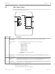
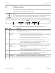
The DSP matrix mixer; the brains of the PLENA matrix system. It has no external controls on
the unit itself. To control this unit it requires either connection to the call station and /or wall
control panel, or a online connection to the PC GUI.
Notice!
It is impossible to control zone volume levels without one of the following; wall control panel,
PC or iOS GUI. Refer to PC GUI software, page 16 to install the PC GUI, if needed.
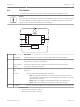
Mic/Line I npu ts
+48V
Line Input s
Bus y
Net wor k
Signal /Clip
Outpu ts
1 2 3
4 5 6 7
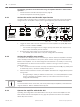
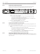
Refer to the following table to check the indicators of the functionality in use.
Number Item Description
1 Power on LED Flashes (green) during power on and initialization. It becomes solid (green) as soon
the unit/system is ready-for-use.
2 Mic./Line 1‑4
level LED
– 2 x bi‑color LED per microphone/line input (4x) indicating:
– Microphone +48 V phantom power supply LED: On (yellow), when phantom
power supply is supplied to the connected microphone.
– Signal presence/Clip LED: On, when applied signal is -40dB from clip
(green), -3dB from clip (amber), 0dB (red = clip).
3 Line input LED – Bi‑color LED per background music source input (3x) indicating:
– Signal presence/Clip LED: On, when applied signal is -40dB from clip
(green), -3dB from clip (amber) or 0dB (red = clip).
4 Call station LED
+ signal
precense / clip
LED
– 2 x bi‑color LED on the call-station input indicating:
– Announcement active LED. On (yellow), when a call station is making an
announcement.
– Signal presence/Clip LED: On, when applied signal is -40dB from clip
(green), -3dB from clip (amber) or 0dB (red = clip).
5 Output 1‑8 LED – Bi‑color LED per zone output (8x) indicating:
– Signal presence/Clip LED: On, when applied signal is -40dB from clip
(green), -3dB from clip (amber) or 0dB (red = clip).
6 RS485 LED Indicates RS485 bus communication (call stations, wall control panels).
7 Network LED Indicates network/PC communication (e.g. communication with the PC GUI).
8.5
PLENA matrix Operation | en 39
Bosch Security Systems B.V. Operation manual 2013-06 | V1.0 |