VG4 Modular Camera Series VG4 Series en Installation Manual
VG4 Modular Camera Series Table of Contents | en 3 Table of Contents 1 Safety 6 1.1 Important Safety Instructions 6 1.2 Safety Precautions 8 1.3 Important Safeguards for Pressurized Units 8 1.4 Important Notices 8 1.5 Customer Support and Service 2 Installing the Pendant Arm Wall, Corner, and Mast (Pole) Mounts 13 2.1 Unpacking 13 2.1.1 Parts List 13 2.1.2 Description 15 2.1.3 Tools Required 15 2.2 Pre-installation Checklist 15 2.3 Mount Power Supply Box 16 2.
en | Table of Contents VG4 Modular Camera Series 3.5 Installing the VG4-A-9230 Roof Parapet Mount 52 3.6 Installing the VG4-A-9543 Pipe Mount 55 3.7 Wire the Pipe Interface Board 57 3.7.1 Wiring for Multiple AutoDomes 58 3.7.2 Connecting Wires to the Pipe Interface Board 58 3.8 Assemble the Pendant in Packing Box 60 3.9 Attach Pendant to Pipe and Tighten 62 3.10 Make Connections in the Power Supply Box 63 3.10.1 Connections for Fiber Optic Models 63 3.
VG4 Modular Camera Series Table of Contents | en 5 5.6 Audio Cables 94 6 Alarms and Relay Connections 96 6.1 Alarm Inputs 96 6.2 Configuring Supervised Alarms (inputs 1 and 2) 96 6.2.1 Configuring a Normally Open Supervised Alarm 96 6.2.2 Configuring a Normally Closed Supervised Alarm 97 6.3 Configuring Non-supervised Alarms (inputs 1 through 7) 98 6.3.1 Configuring a Normally Open Non-supervised Alarm 98 6.3.2 Configuring a Normally Closed Non-supervised Alarm 98 6.
en | Safety VG4 Modular Camera Series 1 Safety 1.1 Important Safety Instructions Read, follow, and retain for future reference all of the following safety instructions. Heed all warnings on the unit and in the operating instructions before operating the unit. 1. Cleaning - Unplug the unit from the outlet before cleaning. Follow any instructions provided with the unit. Generally, using a dry cloth for cleaning is sufficient, but a moist fluff-free cloth or leather shammy may also be used.
VG4 Modular Camera Series Safety | en 7 11. Power sources - Operate the unit only from the type of power source indicated on the label. Before proceeding, be sure to disconnect the power from the cable to be installed into the unit. – For battery powered units, refer to the operating instructions. – For external power supplied units, use only the recommended or approved power supplies. – For limited power source units, this power source must comply with EN60950.
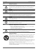
1.2 en | Safety VG4 Modular Camera Series Safety Precautions DANGER! This symbol indicates an imminently hazardous situation such as “Dangerous Voltage” inside the product. If not avoided, this will result in an electrical shock, serious bodily injury, or death. WARNING! Indicates a potentially hazardous situation. If not avoided, this could result in serious bodily injury or death. CAUTION! Indicates a potentially hazardous situation. If not avoided, this may result in minor or moderate injury.
VG4 Modular Camera Series Safety | en 9 Camera lens - An assembled camera lens in the outdoor housing must comply and be tested in accordance with UL/IEC60950. Any output or signal lines from the camera must be SELV or Limited Power Source. For safety reasons the environmental specification of the camera lens assembly must be within the environmental specification of -10 °C (14 °F) to 50 °C (122 °F).
en | Safety VG4 Modular Camera Series Outdoor signals - The installation for outdoor signals, especially regarding clearance from power and lightning conductors and transient protection, must be in accordance with NEC725 and NEC800 (CEC Rule 16-224 and CEC Section 60). Permanently connected equipment - Incorporate a readily accessible disconnect device in the building installation wiring. Pluggable equipment - Install the socket outlet near the equipment so it is easily accessible.
VG4 Modular Camera Series Safety | en 11 INFORMATIONS FCC ET ICES (commercial applications) (modèles utilisés aux États-Unis et au Canada uniquement, CLASSE A) Ce produit est conforme aux normes FCC partie 15. la mise en service est soumises aux deux conditions suivantes: – cet appareil ne peut pas provoquer d'interférence nuisible et – cet appareil doit pouvoir tolérer toutes les interférences auxquelles il est soumit, y compris les interférences qui pourraient influer sur son bon fonctionnement.
1.5 en | Safety VG4 Modular Camera Series Customer Support and Service If this unit needs service, contact the nearest Bosch Security Systems Service Center for authorization to return and shipping instructions. Service Centers USA Telephone: 800-366-2283 or 585-340-4162 Fax: 800-366-1329 Email: cctv.repair@us.bosch.com Customer Service Telephone: 888-289-0096 Fax: 585-223-9180 Email: security.sales@us.bosch.
VG4 Modular Camera Series Installing the Pendant Arm Wall, Corner, and Mast (Pole) Mounts | en 2 Installing the Pendant Arm Wall, Corner, and Mast (Pole) Mounts 2.1 Unpacking 13 This equipment should be unpacked and handled with care. If an item appears to have been damaged in shipment, notify the shipper immediately. Verify that all the parts listed in the Parts List below are included. If any items are missing, notify your Bosch Security Systems Sales or Customer Service Representative.
en | Installing the Pendant Arm Wall, Corner, and Mast (Pole) Mounts VG4 Modular Camera Series The following figures depict the parts (some optional) for a pendant arm wall, corner, or mast mount.
VG4 Modular Camera Series 2.1.2 Installing the Pendant Arm Wall, Corner, and Mast (Pole) Mounts | en 15 Description Chapter 2 details how to install an AutoDome Pendant Arm to a wall, a corner, or to a mast (pole). Any variations to the installation procedures are noted. See Chapter 3 for a Roof (Parapet) or Pipe mount installation or Chapter 4 for an In-Ceiling mount installation. 2.1.3 Tools Required – 5 mm Allen wrench (supplied) – Small, straight-blade screwdriver - 2.5 mm (0.1 in.) – No.
en | Installing the Pendant Arm Wall, Corner, and Mast (Pole) Mounts 6. VG4 Modular Camera Series Choose the appropriate mounting kit to use, depending on the location of the AutoDome, either wall mount, corner mount, or mast (pole) mount. If the kit contains a Power Supply Box, refer to Section 2.3 Mount Power Supply Box, page 16. If you are using the Mounting Plate with a 24 V VG4 AutoDome, refer to Section 2.8 Installing the VG4-A-ARMPLATE, page 27.
VG4 Modular Camera Series 4. Installing the Pendant Arm Wall, Corner, and Mast (Pole) Mounts | en 17 Secure the Power Supply Box to the mounting surface. – For a Wall installation: Use four (4) corrosion-resistant, stainless steel studs (not – For a Corner installation: Secure the Corner Plate to the wall corner using four (4) supplied). Then proceed to Step 5 below. studs (not included). Then proceed to Step 5 below.
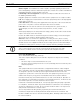
en | Installing the Pendant Arm Wall, Corner, and Mast (Pole) Mounts 1. VG4 Modular Camera Series Route all video, control, and alarm wires through the conduit fitting on the right side of the power box. See Section 5 Cable and Wire Standards, page 85, for coax, UTP, and fiber optic specifications and distances. 2. Route the high voltage 115/230 VAC lines through the conduit fitting on the left side of the box.
VG4 Modular Camera Series 7. Installing the Pendant Arm Wall, Corner, and Mast (Pole) Mounts | en 19 If you are connecting alarm inputs and outputs, attach the supplied 4- and 6-pin Alarm Connectors with flying lead wires to the appropriate incoming alarm wires. BROWN 3 ORANGE 4 GREEN PIN 1 2 3 4 5 6 Figure 2.3 1 P102 WHITE BROWN ORANGE GREEN P103 1 2 3 4 A1 A2 GND WHITE 2 N.O. COM N.C.
en | Installing the Pendant Arm Wall, Corner, and Mast (Pole) Mounts 2.4.1 VG4 Modular Camera Series Power Supply Box Connections The following figure is a detailed illustration of the Pendant Arm Power Supply Box, which includes the fuse specifications. XF103 XF102 P101 NC 24V 123 P106 GND TXD RXD P105 C+ C- 6 5 4 3 2 1 Figure 2.
VG4 Modular Camera Series Installing the Pendant Arm Wall, Corner, and Mast (Pole) Mounts | en 21 The following table lists the Power Supply Box connectors: No.
en | Installing the Pendant Arm Wall, Corner, and Mast (Pole) Mounts VG4 Modular Camera Series To properly wire the incoming high voltage and the outgoing low voltage lines, refer to this table: No. Connector Pin 1 Ground Grounding Screw P101 115/230 VAC Power In Line P107 24 VAC Power Out Table 2.2 1.
VG4 Modular Camera Series 6. Installing the Pendant Arm Wall, Corner, and Mast (Pole) Mounts | en 23 Route the 24 VAC outgoing power supply wires into the VG4-PA0 power supply box through the conduit fitting on the left side of the box. 7. Cut and trim the 24 VAC power and ground wires with sufficient slack to reach their connector terminal in the box, but not so long as to be pinched by or to obstruct closing the cover door. 8.
2.6 en | Installing the Pendant Arm Wall, Corner, and Mast (Pole) Mounts VG4 Modular Camera Series Attach Pendant Arm to Power Supply Box The bottom hinge pin of the Pendant Arm is provided with a Hinge Pin Stop to hold the hinge open while attaching the arm to the Power Supply Box. 1. Compress the bottom hinge pin by pushing the pin lever downward and rotating it behind the Hinge Pin Stop. Figure 2.9 2.
VG4 Modular Camera Series 2.7 Installing the Pendant Arm Wall, Corner, and Mast (Pole) Mounts | en 25 Make Connections in Power Supply Box Refer to Table 2.2, Page 22 to locate the various connectors in the power supply box and make the following connections detailed below. 123 Figure 2.10 1. Pendant Arm connections to Power Supply Box Attach the earth ground wire (item 1 in the illustration above) to the grounding screw on the left side of the power box. 2.
en | Installing the Pendant Arm Wall, Corner, and Mast (Pole) Mounts 5. VG4 Modular Camera Series Connect the incoming video coax cable to the BNC connector from the Pendant Connector Harness and slide its plastic cover over the connector. 6. To connect alarm inputs and relay outputs, connect the 4-pin Alarms Out, the 6-pin Alarms In and the 7-pin Relay connectors from the Pendant Connector Harness to their mating connectors, installed previously, to the incoming alarm wires. 7.
VG4 Modular Camera Series 9. Installing the Pendant Arm Wall, Corner, and Mast (Pole) Mounts | en 27 If using UTP for video or Ethernet, connect the incoming RJ45 video connector, installed previously, to its mating connector from the Pendant Connector Harness. See Section 5 Cable and Wire Standards, page 85 for connections and specifications. 10. Attach the grounding strap of the Pendant Arm to the Power Supply Box. See Figure 2.10, Page 25. 11.
en | Installing the Pendant Arm Wall, Corner, and Mast (Pole) Mounts d. VG4 Modular Camera Series Once the Mounting Plate (item 1, below) is attached to the Mast Plate (item 2), connect the right angle conduit (item 3) to the Mounting Plate through the empty conduit hole as shown below: 3. 2.8.1 Ensure that the mounting plate is secure.
VG4 Modular Camera Series 2. Installing the Pendant Arm Wall, Corner, and Mast (Pole) Mounts | en 29 Open the top hinge by pushing its pin lever up and holding it. Note: Both Hinge Pins must be fully compressed to open (unlock) the hinges of the Pendant Arm and before proceeding to the next step. 3. While continuing to hold the top hinge pin open, align the top and bottom hinges of the Pendant Arm to their mating points on the Mounting Plate. See Figure 2.12, above, for an illustration. 4.
en | Installing the Pendant Arm Wall, Corner, and Mast (Pole) Mounts 1. VG4 Modular Camera Series Route all incoming wires through one of the conduits at the bottom of the Mounting Plate. For a mast mount, route all wires through the right-angle conduit. 2. 3. Attach the water-tight plug to the other conduit. Attach the grounding spade terminal (item 1, below) to one of the spade terminals inside the Mounting Plate. Figure 2.14 Ref. 1 2 3 4.
VG4 Modular Camera Series Installing the Pendant Arm Wall, Corner, and Mast (Pole) Mounts | en 31 12. Connect the incoming alarms wires to the flying leads coming from the 6-pin Alarm Inputs cable (cable 7). 13. Connect the incoming serial communication wires to the 6-pin mating connector supplied with the VG4-A-ARMPLATE kit. Ensure that the 100 Ω resistor remains connected to the Biphase C- and the Biphase C+ terminals.
en | Installing the Pendant Arm Wall, Corner, and Mast (Pole) Mounts 4. VG4 Modular Camera Series Align the yellow locking tab on the base of the Camera Module to the yellow label on the CPU board and gently seat the camera into its connector. Figure 2.15 5. Align and Attach Camera Module Rotate the yellow locking tab of the Camera Module clockwise (approximately 60 degrees) until the Camera Module locks in place.
VG4 Modular Camera Series 2.10 Installing the Pendant Arm Wall, Corner, and Mast (Pole) Mounts | en 33 Attach Pendant to Arm and Tighten NOTICE! Before attaching the AutoDome Pendant, visually inspect the dome and arm connectors for any blocked pin holes or bent pins. 1. Tilt the bottom of the dome toward the pendant arm base and place the mounting hook, located on top of the dome housing, over the recessed hinge pin of the arm. a b Figure 2.17 1 2 2a 2b 3 4 Attach Pendant to Arm Tilt up.
en | Installing the Pendant Arm Wall, Corner, and Mast (Pole) Mounts 4. VG4 Modular Camera Series Hold the Pendant housing in position while tightening the two (2) 5-mm Allen head mounting screws on top of the housing to 10-12 N-m (90-105 in.-lbs). CAUTION! You must tighten the two mounting screws to a minimum torque of 10-12 N-m (90-105 in.-lbs) to ensure a proper seal between the arm and the housing.
VG4 Modular Camera Series 2.11 Installing the Pendant Arm Wall, Corner, and Mast (Pole) Mounts | en 35 Installing the Pressurized Environmental Housing The VG4 Pressurized Environmental Housing provides maximum protection for CCTV cameras and lenses. The charge of dry nitrogen inside the housing eliminates the effects of moisture, dust, insects, and corrosive exhaust fumes.
en | Installing the Pendant Arm Wall, Corner, and Mast (Pole) Mounts 2.11.3 VG4 Modular Camera Series Required Equipment To pressurize the housing, you need the following: – A tank of dry nitrogen Nitrogen is a readily available gas; check your local yellow pages for a medical or industrial gas provider. If the tank is to be carried from location to location, a size of 1 cubic meter (40 cubic feet) is recommended. This tank size should be enough to refill 30 individual housings.
VG4 Modular Camera Series 2.11.4 Installing the Pendant Arm Wall, Corner, and Mast (Pole) Mounts | en 37 Attaching the Housing to the Arm NOTICE! Before attaching the AutoDome Pendant, visually inspect the dome and arm connectors for any blocked pin holes or bent pins. 1. Tilt the bottom of the dome toward the pendant arm base and place the mounting hook, located on top of the dome housing, over the recessed hinge pin of the arm. Figure 2.20 1 2 3 4 2.
en | Installing the Pendant Arm Wall, Corner, and Mast (Pole) Mounts Figure 2.21 VG4 Modular Camera Series Tighten Pendant Connection 1 Rotate down to engage dome connector. 2 Tighten the two (2) mounting screws to a minimum torque of 10-12 N-m (90-105 in.-lbs). CAUTION! You must tighten the two mounting screws to a minimum torque of 10-12 N-m (90-105 in.-lbs) to ensure a proper seal between the arm and the housing. 2.11.
VG4 Modular Camera Series 3. Installing the Pendant Arm Wall, Corner, and Mast (Pole) Mounts | en 39 Using a thin screwdriver press and hold the red calibration switch, located on the opposite side of the LED. Once the sensor is calibrated and the data is permanently stored, the LED shuts off and you can release the calibration switch. Figure 2.22 1 2 3 4. 2.11.6 Location of the Calibration Switch Calibration Switch Schrader Fill Valve LED Turn the power off to the VG4 unit.
en | Installing the Pendant Arm Wall, Corner, and Mast (Pole) Mounts 7. VG4 Modular Camera Series Place the bubble support ring over the bubble and align the eight (8) captive screws with the threaded inserts on the plastic gasket ring. Figure 2.24 8. Attach Support Ring Loosely tighten the captive screws with the T25 pin-in Torx tool using a diametrically opposed tightening pattern, until the gap between the bubble support ring and the housing closes.
VG4 Modular Camera Series 9. Installing the Pendant Arm Wall, Corner, and Mast (Pole) Mounts | en 41 Tighten the screws again, using the same diametrical pattern, to a torque of 0.90 N-m (8 in.-lbs). Use a dial-indicator torque screwdriver to check the torque. 10. Begin a second round of tightening, using the same diametrical pattern, until the screws reach a torque of 1.58 N-m (14 in.-lbs). 11. Continue tightening the screws, using the same diametrical pattern, to reach a torque of 2.26 N-m (20 in.
en | Installing Roof Parapet and Pipe Mounts VG4 Modular Camera Series 3 Installing Roof Parapet and Pipe Mounts 3.1 Unpacking This equipment should be unpacked and handled with care. If an item appears to have been damaged in shipment, notify the shipper immediately. Verify that all the parts listed in the product's Parts List below are included. If any items are missing, notify your Bosch Security Systems Sales or Customer Service Representative. See See Section 1.
VG4 Modular Camera Series Installing Roof Parapet and Pipe Mounts | en 43 Roof Parapet and Pipe Mount Parts List Trim Skirt (optional) Power Supply Power Supply cover Roof Parapet Mount Pipe Mount Assembly Interface Module Environmental Shield (optional) Pressurized Environmental Housing (optional) Pendant Housing COMMS Module Thermal Module (optional) CPU Module Camera Module Dome Bubble Bubble Support Ring for Pressurized Environmental Housing (optional) Bosch Security Systems, Inc.
en | Installing Roof Parapet and Pipe Mounts 3.1.2 VG4 Modular Camera Series Description Chapter 3 details how to install a VG4 AutoDome to a Roof Parapet or to a Pipe mount. Any differences to the installation between these two mounting systems are noted. See Chapter 2 if you are installing a Pendant Arm to a Wall, Corner, or Mast (or pole) or see Chapter 4 if you are mounting an In-ceiling AutoDome. The VG4-A-9230 Series are stationary mounts intended for rooftop parapet vertical walls.
VG4 Modular Camera Series 6. Installing Roof Parapet and Pipe Mounts | en 45 Choose the appropriate mounting kit to use depending on the location of the AutoDome: Parapet (Roof) mount or the Pipe mount. CAUTION! Select a rigid mounting location to prevent excessive vibration to the AutoDome camera. 3.3 Mount Power Supply Box Before mounting the Power Supply Box decide if you will be wiring the box through the holes in the bottom or back of the box.
en | Installing Roof Parapet and Pipe Mounts 3.3.1 VG4 Modular Camera Series Attach Cover Door 1. Compress the bottom hinge pin by pushing the pin lever down and then rotate it behind the Hinge Pin Stop. The power box Cover Door provides a Hinge Pin Stop to hold the bottom hinge open while attaching the door. (FUSE) o (FUSE) HTR (FUSE) DOME 90 24V NC 24V GND TXD RXD Figure 3.2 1 2 3 4 2.
VG4 Modular Camera Series 3.4 Installing Roof Parapet and Pipe Mounts | en 47 Route Wires and Attach Connectors Power wires must be routed to the left (front) side of the Power Supply Box through a separate conduit. All video, control, and alarm wires must be routed through a second conduit to the right side of the box. See Section 5 Cable and Wire Standards, page 85 for methods of transmitting video and data, and for wire specifications.
en | Installing Roof Parapet and Pipe Mounts – VG4 Modular Camera Series The second method is to bypass the Power Supply Box and route the video, control, and alarm wires directly to the Interface Board. You connect only the power wires inside the Power Supply Box.
VG4 Modular Camera Series 3.4.1 Installing Roof Parapet and Pipe Mounts | en 49 Wiring the Power Supply Box 1. Route the high voltage 115/230 VAC lines through the conduit fitting on the left side of the box. NOTICE! The Power Supply Box with transformer comes with a barrier that separates the high voltage side on the left from the low voltage 24 VAC side on the right. 2.
en | Installing Roof Parapet and Pipe Mounts 3. VG4 Modular Camera Series Route the control wires from the Power Supply to the Pipe Interface Board. Then attach the supplied six (6) pin control data connector to the wires in the Power Supply Box. (FUSE) (FUSE) HTR (FUSE) DOME (GND) 24V NC 24V GND TXD RXD 1 2 3 4 F.01U.162.025 | 6.0 | 2010.
VG4 Modular Camera Series 3.4.3 Installing Roof Parapet and Pipe Mounts | en 51 Power Supply Box Connections The following figure is a detailed illustration of the Roof or Pipe Mount Power Supply Box, 123 XF102 CONTROL IN/OUT P106 GND T XD RXD C+ C- 6 5 4 3 2 1 1 2 3 4 CONTROL TO DOM ME P105 GND T XD RXD C+ J103 J103 (LED) 24V NC 24V (FUSE)) DOME HTR P107 XF101 (FUSE)) P101 (FUSE)) J101 1 J102 5 4 3 2 1 XF103 which includes the fuse specifications.
en | Installing Roof Parapet and Pipe Mounts VG4 Modular Camera Series The following table lists the Power Supply Box connectors: No.
VG4 Modular Camera Series 2. Installing Roof Parapet and Pipe Mounts | en 53 Prepare the mounting surface for the type of fastener by drilling holes for the mounting anchors as required. Figure 3.6 Parapet Wall Mount Bracket and Roof Mount Plate 1 2 3 Pipearm 4 Parapet Wall Bracket 5 3/8-16 SS Hex Head Bolt (supplied) 6 Apply sealant around each fastener hole Roof Mount Plate Use a minimum of six (6) fasteners (not supplied). Eight (8) fastener holes shown.
en | Installing Roof Parapet and Pipe Mounts 6. VG4 Modular Camera Series Remove the End Cap from the front of the arm and feed the video, control, and power wires up through the bottom of the pipe arm and out the front end. Figure 3.7 1 2 3 4 5 7. VG4-A-9230 Parapet Mount End Cap with O-ring Parapet Pipe Arm 1/4-20 SS Cap Screw Down Pipe 10-24 SS Pan Head Screw Fold the video, control, and power wires back at the front end of the arm and route them down and out through the Down Pipe.
VG4 Modular Camera Series Installing Roof Parapet and Pipe Mounts | en 55 11. Run a bead of RTV Silicon sealant around the down pipe/Dome Cap interface to seal any gaps between the down pipe and the Dome Cap. 12. Proceed to Section 3.7 Wire the Pipe Interface Board, page 57. NOTICE! Use a guy-wire to aid in stabilizing the Parapet Arm. Replace the 1/4 inch cap screw with a threaded 1/4-inch stainless steel eye bolt (not supplied).
en | Installing Roof Parapet and Pipe Mounts 3. VG4 Modular Camera Series Attach pipe (not supplied) to the Top-mounting Flange. WARNING! You must thread the pipe onto the Top-mounting Flange until it is tight. Failure to do so can result in damage, serious injury or death. 4. Route the power, video, control, and alarm wires through the Top-Mounting Flange and down the pipe. 5. Wrap at least five layers of Teflon tape around the threads. 6.
VG4 Modular Camera Series 3.7 Installing Roof Parapet and Pipe Mounts | en 57 Wire the Pipe Interface Board This section provides instructions for connecting wires and cables to the Pipe Interface Board, as illustrated below. See Section 5 Cable and Wire Standards, page 85 for cable and wiring recommendations and specifications. BNC P105 1 2 3 4 5 J102 6 7 P102 5 4 3 2 1 3 P101 AGND A7 A6 A5 A4 A3 P103 AGND OUT 3 OUT 2 OUT 1 P104 6 2 P107 1 2 1 J101 P106 Figure 3.
en | Installing Roof Parapet and Pipe Mounts 3.7.1 VG4 Modular Camera Series Ref.
VG4 Modular Camera Series 2. Installing Roof Parapet and Pipe Mounts | en 59 Attach the control data in/out wires to their respective terminals on the P105 connector on the Pipe Interface Board. See Figure 3.10, Page 57, for an illustration of these connections. 3. Connect the 24 VAC power wires to the P101 connector on the Pipe Interface Board. If this model has a heater, connect the 24 VAC heater power wires to connector P107.
en | Installing Roof Parapet and Pipe Mounts 6. VG4 Modular Camera Series Insert the Pipe Interface Board into the down pipe and fasten the three (3) retaining screws to secure the board to the Dome Cap. CAUTION! Be careful not to strip the threads when tightening the Pipe Interface Board retaining screws. Figure 3.12 1 2 3 3.
VG4 Modular Camera Series Installing Roof Parapet and Pipe Mounts | en 61 3. Remove the Camera Module from its packing box, and remove the protective plastic bag. 4. Align the yellow locking tab on the Camera Module base to the (yellow) label on the CPU board, and gently seat the camera onto its connector. Figure 3.13 5. Align Lock Tab and Install Camera Module Rotate the base of the Camera Module clockwise (approximately 60 degrees) until the yellow tab locks in place.
3.9 en | Installing Roof Parapet and Pipe Mounts VG4 Modular Camera Series Attach Pendant to Pipe and Tighten 1. Before attaching the Pendant, visually inspect the Pendant dome and the Interface Board connectors for any blocked pin holes and bent pins. 2. Tilt the Pendant enough to place its mounting hook on top of the its housing, over the recessed hinge pin of the Dome Cap. a b c Figure 3.15 1 2 2a 2b 2c 3 4 Pendant to Roof / Pipe Mount Attachment Tilt Dome. Hook and drop.
VG4 Modular Camera Series 5. Installing Roof Parapet and Pipe Mounts | en 63 Hold the housing firmly in position and alternately tighten the two (2) 5-mm Allen head mounting screws from above to a torque value of 10-12 N-m (90-105 in.-lbs). CAUTION! You must tighten the two mounting screws to a minimum torque of 10-12 N-m (90-105 in.-lbs) to ensure a proper seal between the arm and the housing. 6.
en | Installing Roof Parapet and Pipe Mounts VG4 Modular Camera Series Removing the Pendant Bubble To service the AutoDome Pendant, use the following procedure to remove the Bubble: 1. Using both hands, apply a firm counterclockwise (looking up at the dome) rotational force on the Pendant Bubble Assembly to set the bubble latch. 2. Insert a small (2 mm) straight blade screw driver into the release opening in the bubble trim-ring to release the lock, and then remove the screwdriver. Figure 3.16 3.
VG4 Modular Camera Series 3.11 Installing Roof Parapet and Pipe Mounts | en 65 Installing the Pressurized Environmental Housing The VG4 Pressurized Environmental Housing provides maximum protection for CCTV cameras and lenses. The charge of dry nitrogen inside the housing eliminates the effects of moisture, dust, insects, and corrosive exhaust fumes.
en | Installing Roof Parapet and Pipe Mounts 3.11.3 VG4 Modular Camera Series Required Equipment To pressurize the housing, you need the following: – A tank of dry nitrogen Nitrogen is a readily available gas; check your local yellow pages for a medical or industrial gas provider. If the tank is to be carried from location to location, a size of 1 cubic meter (40 cubic feet) is recommended. This tank size should be enough to refill 30 individual housings.
VG4 Modular Camera Series 3.11.4 Installing Roof Parapet and Pipe Mounts | en 67 Attaching the Housing to the Pipe 1. Before attaching the housing, visually inspect the dome and the Interface Board connectors for any blocked pin holes and bent pins. 2. Tilt the housing enough to place its mounting hook on top of the its housing, over the recessed hinge pin of the Dome Cap. c Figure 3.18 1 2 3 4 5 3.
en | Installing Roof Parapet and Pipe Mounts 5. VG4 Modular Camera Series Hold the housing in position while tightening the two (2) 5-mm Allen head mounting screws on top of the housing to 10-12 N-m (90-105 in.-lbs). Figure 3.19 Tighten Pendant Connection 1 Rotate down to engage dome connector. 2 Tighten the two (2) mounting screws to a minimum torque of 10-12 N-m (90-105 in.-lbs). CAUTION! You must tighten the two mounting screws to a minimum torque of 10-12 N-m (90-105 in.
VG4 Modular Camera Series 3.11.6 Installing Roof Parapet and Pipe Mounts | en 69 Calibrating the Pressure Sensor The VG4 Pressurized Environmental Housing features an internal low-pressure sensor alarm which must be calibrated to the local atmospheric pressure. The heater/blower/pressure sensor power must be connected to do calibration. You must perform the calibration procedure within four (4) minutes of powering up the VG4 unit or the sensor will not store the calibration data.
en | Installing Roof Parapet and Pipe Mounts 3.11.7 VG4 Modular Camera Series Attaching the Bubble to the Housing 1. Remove the bubble from the box and then remove the bubble from the protective plastic bag. 2. Disengage the four tabs from the white trim skirt ring that surrounds the bubble. Then, move the trim skirt ring towards the bubble opening to remove. Figure 3.21 3. Bubble with Trim Skirt Ring Discard the trim skirt ring.
VG4 Modular Camera Series 8. Installing Roof Parapet and Pipe Mounts | en 71 Loosely tighten the captive screws with the T25 pin-in Torx tool using a diametrically opposed tightening pattern, until the gap between the bubble support ring and the housing closes. Start tightening screw 1, then tighten screw 2. Next, tighten screw 3 and continue to screw 4. Continue tightening the screws in this pattern. Note: Make sure not to overtighten the screws. Figure 3.23 9.
en | Installing Roof Parapet and Pipe Mounts 3.11.8 VG4 Modular Camera Series Pressurizing the Housing The VG4 Pressurized Environmental Housing can maintain a maximum internal pressure of 75.84 kPa (11 psi) ± 5%. Above 75.84 kPa (11 psi), the pressure relief valve cracks and then seats at a pressure of 65.50– 68.95 kPa (9.5–10 psi). Follow these steps to pressurize the housing: 1. Set the gauge on the regulator to 86.18 kPa (12.5 psi). 2.
VG4 Modular Camera Series Installing the In-Ceiling Mount | en 4 Installing the In-Ceiling Mount 4.1 Unpacking 73 This equipment should be unpacked and handled with care. If an item appears to have been damaged in shipment, notify the shipper immediately. Verify that all the parts listed in the product's Parts List below are included. If any items are missing, notify your Bosch Security Systems Sales or Customer Service Representative. See See Section 1.
en | Installing the In-Ceiling Mount VG4 Modular Camera Series The following figure depicts the parts for the in-ceiling mount. Interface Module In-ceiling Housing Comms Module CPU Module Camera Module Bubble (clear or tinted) 4.1.2 Description This chapter details how to install the AutoDome in an In-Ceiling Mount. The In-Ceiling AutoDome system is suitable for use in environmental air spaces.
VG4 Modular Camera Series 4.2 Installing the In-Ceiling Mount | en 75 Pre-installation Check List 1. Determine the location and distance for the power supply box based on its voltage and current consumption. See Section 5 Cable and Wire Standards, page 85 for specifications. 2. Install all rough wiring including: power, control, video, alarms I/O, relay I/O, and fiber optic cabling. WARNING! 24 VAC Class 2 power supply only. 3.
4.5 en | Installing the In-Ceiling Mount VG4 Modular Camera Series Prepare Suspension Ceiling for Installation 1. Choose the desired location to mount the dome, and remove an adjacent ceiling tile. 2. Loosen the four (4) securing screws, located in the corners of the Bracket Assembly, enough to hold the suspension bars but still allowing adjustment during installation. 3. Place the Bracket Assembly over the ceiling tile, which is used to mount the In-Ceiling AutoDome.
VG4 Modular Camera Series 5. Installing the In-Ceiling Mount | en 77 Tighten the four (4) securing screws to the Bracket Assembly. Figure 4.4 Tighten Bracket Securing Screw 6. Secure the Bracket Assembly to an overhead securing point with a safety wire. Figure 4.5 Secure Bracket Assembly Bosch Security Systems, Inc. Installation Manual F.01U.162.025 | 6.0 | 2010.
4.6 en | Installing the In-Ceiling Mount VG4 Modular Camera Series Wire the Interface Box The Interface Box can be wired through the top or side. Use the supplied rubber plug to seal the hole which will not be used to route wires.
VG4 Modular Camera Series 7. Installing the In-Ceiling Mount | en 79 To connect alarm inputs and outputs, attach the supplied 6-pin Alarms In and the 4-pin Alarms Out connector plugs with flying leads to the appropriate alarm wires. Then connect the plugs to their mating connectors P103 and P102 in the Interface Box. BROWN 3 ORANGE 4 GREEN WHITE BROWN ORANGE P103 GREEN 1 2 3 4 5 6 7 A2 GND PIN 1 2 3 4 5 6 P102 A1 WHITE 2 N.O. COM N.C. PIN 1 YELLOW BLUE P104 Figure 4.
en | Installing the In-Ceiling Mount 4.6.1 VG4 Modular Camera Series Interface Box Connections The following figure is a detailed illustration of the In-ceiling Interface box. J101 P101 24VAC 24VAC J102 J103 P105 C- C+ RXD (+) TXD (-) SIG GND P104 P102 P103 OUT1 OUT2 OUT3 AGND A3 A4 A5 A6 A7 AGND NO COM NC 1 2 3 4 A1 A2 AGND Figure 4.
VG4 Modular Camera Series 4.7 Installing the In-Ceiling Mount | en 81 Attach Housing to the Interface Box The In-Ceiling Housing is attached to the Interface Box and secured by two (2) thumbscrews. Figure 4.9 1. Attach Housing to Interface Box Insert the In-ceiling housing through the hole in the ceiling to verify that the edge of the hole support the unit. Then remove the housing from the hole. 2. Align the ball studs of the In-Ceiling Housing to the Stud Retainers on Interface Box and attach.
4.8 en | Installing the In-Ceiling Mount VG4 Modular Camera Series Secure Housing to Ceiling The In-ceiling Housing is secured to the ceiling by two (2) screw clamps. 1. Insert the In-ceiling Mount Assembly through the hole in the ceiling. 2. Tighten both clamps using a #2 Phillips screwdriver, to secure the housing to the ceiling. 41.7 MAX. 1.64 CEILING 12.7 MIN. 0.50 CEILING mm inches Figure 4.
VG4 Modular Camera Series 4.9 Installing the In-Ceiling Mount | en 83 Align and Install Camera Module The Camera Module connector attaches to the In-Ceiling Housing CPU board. 1. Align the yellow locking tab on the base of the Camera Module to the yellow label on the CPU Module and press the camera base onto its connector. 2. Then rotate the camera clockwise (approximately 60 degrees) until it locks in position. Figure 4.12 4.
en | Installing the In-Ceiling Mount VG4 Modular Camera Series Bubble Removal To service the In-Ceiling AutoDome, use the following procedure to remove the Bubble: 1. Loosen the lockscrew (item 1 in the illustration below) in the trim ring using a P1 or smaller Phillips screwdriver until the bubble can rotate freely. 2. Then rotate the bubble counterclockwise approximately 1/4 turn until it releases from the In-Ceiling Housing. See the figure below for an illustration. Figure 4.14 F.01U.162.
VG4 Modular Camera Series Cable and Wire Standards | en 5 Cable and Wire Standards 5.1 Power 85 115/230 VAC Copper Wire 5.2 To comply with local codes. Wire Distance Guide for Pendant 24 V to AutoDome INDOOR ANALOG 100 Series 200, 300 Series 500 Series VA / Watts 14 AWG (2.5 mm) 16 AWG (1.5 mm) 18 AWG (1.0 mm) 14 /7.
en | Cable and Wire Standards VG4 Modular Camera Series Cable Compensation Maximum Distances Video Only Bilinx Control Size O.D. between 4.6 mm (0.181 in.) and 7.9 mm (0.312 in.) Shield Copper braid: 95% Central Conductor Standard copper center Terminal Connector BNC WARNING! Cable compensation (Pre-Comp) does not extend the range of Bilinx control. Pre-Comp is not available to AutoDomes with an IP module.
VG4 Modular Camera Series Cable and Wire Standards | en 87 Ethernet AutoDome Ethernet models are connected to a 10/100 Base-T network either directly or via a hub. Both video and control are transmitted over a standard TCP/IP network using the built-in web server. Cable Type UTP CAT-5 Maximum Distance 100 m (328 ft) Bandwidth 10/100 Base-T Terminal Connector RJ45 WARNING! Do not connect the RJ45 connector unless using UTP video or Ethernet.
en | Cable and Wire Standards VG4 Modular Camera Series Fiber Optic Ethernet Media Converter The fiber optic media converter is designed to transmit 10/100 Mbps Ethernet signals over fiber optic cable using 10/100 Mbps Small Form-factor Pluggable (SFP) modules. The SFP modules are available as multi-mode fiber (MMF) or single-mode fiber (SMF) models with a single SC connector or dual-fiber with an LC connector. Refer to the VG4-SFPSCKT Fiber Optic Media Converter Installation Guide.
VG4 Modular Camera Series Cable and Wire Standards | en 89 The figure below illustrates the connections necessary for Biphase operation. 100 Ω Figure 5.
en | Cable and Wire Standards VG4 Modular Camera Series RS232 (3-wire, full-duplex, single-ended, 50 ft. cable limit) RS232 is a common, single-ended communication protocol used for control. Data transmission via 3-wires (TDX, RXD, common) is from one transmitter to one receiver at relatively slow baud rates (up to 57.6 Kbaud) and short distances up to 50 ft.
VG4 Modular Camera Series Cable and Wire Standards | en 91 RS485 (2-wire (shielded), half-duplex, differential, multi-drop (32 nodes), 4000 ft cable limit) RS485 is capable of controlling a true multi-drop network and is specified for up to 32 drivers and 32 receivers on a single 2-wire bus. The AutoDome uses the 2-wire mode, although RS485 can be connected in a 2- or 4-wire mode. NOTICE! The wire shield must be tied to signal at both ends, if 2-wire twisted pair is used.
en | Cable and Wire Standards Figure 5.7 1 2 3 4 5.5 VG4 Modular Camera Series Position of CPU Switch for RS485 Operation Switch Location LEDs RS485 CPU Module Fiber Optic Module with an RS232/RS422 Controller An AutoDome with a fiber optic module is prewired to operate with Biphase signals only. This section describes the procedures necessary to control a VG4 series AutoDome fitted with a fiber optic kit using an RS232 controller or a Pelco® RS422 controller.
VG4 Modular Camera Series 5.5.2 Cable and Wire Standards | en 93 Configuring the VG4 AutoDome 1. Disconnect the power to the VG4 power supply unit; then open the unit. 2. Remove the green Serial Communications wire from the P106 connector. 3. Remove the 100 Ohm resistor across the C+ and C- pins. 4. Cut the five wires from the green Serial Communications wire mating connector. Ensure that the insulation covers each wire to avoid wires from touching. 5.
en | Cable and Wire Standards VG4 Modular Camera Series 10. Ensure that the VG4 AutoDome is set to receive RS232 commands. – Remove the bubble from the VG4 AutoDome housing. – Locate the protocol switch on the CPU board. – Ensure that the protocol switch is in the left position for RS232 operation. Figure 5.9 1 2 3 4 Position of CPU Switch for RS232 Operation Switch Location LEDs Move Switch to the left for RS232 Operation CPU Module 11. Return the bubble to the AutoDome housing. 12.
VG4 Modular Camera Series Cable and Wire Standards | en 95 Audio Connections 1. Remove the 100 ohm termination resistor from the Biphase terminals. 2. Connect the audio line level source to the Biphase C+ input terminal. 3. Connect the audio signal ground to the Biphase C- input terminal. The following figure illustrates the connections for audio over an IP network Figure 5.
en | Alarms and Relay Connections VG4 Modular Camera Series 6 Alarms and Relay Connections 6.1 Alarm Inputs The AutoDome provides seven alarm inputs. Each input can be activated by dry contact devices such as pressure pads, passive infra-red detectors, door contacts, and similar devices. The table below summarizes the size and distance wires. Wire Size Maximum Distance AWG mm feet meters 22 0.644 500 152.4 18 1.024 800 243.8 Table 6.
VG4 Modular Camera Series 3. Alarms and Relay Connections | en 97 From the AutoDome main menu, select Alarms Setup>Inputs Setup, and set the Alarm Input # to N.O.S. See the table below for contact and condition details. AutoDome Programmed N.O.S. 6.2.2 Contact Alarm Condition Open Normal Closed Alarm Cut or brake Tamper Configuring a Normally Closed Supervised Alarm 1. 2. Install a 2.2 K end-of-line resistor in the alarm circuit.
en | Alarms and Relay Connections 6.3 VG4 Modular Camera Series Configuring Non-supervised Alarms (inputs 1 through 7) You can configure alarms 3 through 7 as non-supervised Normally Open (N.O.) or Normally Closed (N.C.) alarms. 6.3.1 Configuring a Normally Open Non-supervised Alarm 1. Connect the alarm to the appropriate input (1 through 7) and ground at the AutoDome. Figure 6.3 1 2 2. N.O.
VG4 Modular Camera Series 6.4 Alarms and Relay Connections | en 99 Alarm Outputs The AutoDome incorporates two (2) types of alarm outputs: a dry contact relay and three (3) open collector outputs or transistor outputs. 6.4.1 Configuring a Dry Contact Relay The dry contact relay acts like an on/off switch. It has a maximum voltage rating of 2 A @ 30 DC. 1. 2. Connect the appropriate stripped wire to the AutoDome COM connector. Connect the appropriate stripped wire to the N.O. or N.C.
en | Bubble Handling and Cleaning 7 VG4 Modular Camera Series Bubble Handling and Cleaning The bubble is made of Polycarbonate. This material provides high impact resistance. It’s optical clarity is comparable to glass or acrylic, although it’s surface is much softer. Special care is required when handling and cleaning the bubble to avoid scratching it. 7.1 Handling The bubble is packaged with a protective plastic sheet.
VG4 Modular Camera Series A | en 101 Installation Notes for AutoTracker AutoTracker is a feature available with the 500 Series AutoDome. AutoTrack operates by recognizing an individual in motion and zooms-in to approximately 50% of the field of view for an average target height of six feet. For target acquisition, the focal length must be set correctly, and there needs to be at least 1.2 seconds of valid motion for tracking to initially start.
en | A.2 VG4 Modular Camera Series Mount/Mounting Surfaces – Mount the camera in the most stable position. Avoid locations affected by vibrations, such as those caused by a roof-top air conditioner. These vibrations may cause complications when the camera zooms-in on a target. – Use the pendant arm mount, if possible. This mount option provides the most stability for the camera. – A.3 Use guy wires to protect against strong winds if using the parapet mount.
VG4 Modular Camera Series Index | en 103 Index A D alarm connectors 19 alarm inputs 96 dry contact relay 99 non-supervised 98 normally closed non-supervised 98 normally closed supervised 97 normally open non-supervised 98 normally open supervised 96 supervised 96 with in-ceiling mount 79 with parapet roof or pipe mounts 59 with pendant arm, corner or mast mount 19, 26, 31 alarm outputs 99 open collector output 99 with in-ceiling mount 79 with parapet roof or pipe mount 59 with pendant arm, corner or mas
en | Index VG4 Modular Camera Series N R NEMA Certification for pendant arm, corner or mast mount 15 for roof parapet or pipe mount 44 non-supervised alarms 98 relay 99 relay connectors 19 RJ45 78 roof parapet or pipe mount 42, 52 cover door 46 dome cap 54 fiber optic model 63, 68 parts 42 power supply box location 44 wall bracket 53 wall mount bracket 52 routing wires for in-ceiling mount 78 for pendant arm, corner or mast mount 17 for roof parapet or pipe mount 47 RS232 90 RS485 91 P parapet arm
Bosch Security Systems, Inc. 850 Greenfield Road Lancaster, PA 17522 U.S.A. Phone +1 888-289-0096 Fax +1 585-223-9180 www.boschsecurity.com © Bosch Security Systems, Inc.