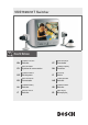
VSS7390/01T Switcher Installation Instructions EN Switcher Manual de Instalação PT Manuel d’installation FR Système de commutation Installationsvejledning DA Installationshandbuch DE Schaltsystem Conmutador FI Switcher Switcher Switcher Installationshandbok SV Switcher Βιβλίο οδηγιών Manuale di istruzioni IT Valitsin Installeringshåndbok NO Installatiehandleiding NL Omskifter Asennusohje Manual de instalación ES Comutador EL Μεταγωγέας
VSS7390/01T Switcher | Installation Manual | Table of Contents 1. SAFETY PRECAUTIONS .........................................................................................................................................................2 1.1 2. 3. IMPORTANT SAFEGUARDS .......................................................................................................................2 1.1.1 FCC Information .............................................................................................
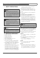
VSS7390/01T Switcher | Installation Manual | Chapter 1 1 EN | 2 SAFETY PRECAUTIONS 10 Danger The lightning flash with arrowhead symbol, within a triangle, is intended to alert the user to the presence of uninstalled “dangerous voltage” within the product's enclosure; that may be of sufficient magnitude to constitute a risk of electric shock to persons.
VSS7390/01T Switcher | Installation Manual | Chapter 1 Caution Danger of explosion if batteries are incorrectly replaced. Replace only with the same or equivalent type. Remark Bosch has a strong commitment towards the environment. This monitor has been designed to respect the environment as much as possible. 1.1.1 FCC Information This equipment has been tested and found to comply with the limits for a Class B digital device, pursuant to part 15 of the FCC Rules.
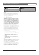
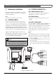
VSS7390/01T Switcher | Installation Manual | Chapter 2 2 Hardware Installation EN | 4 2.2 SYSTEM CONNECTION This chapter describes the installation of the system hardware. For details of operation, see the supplied Operation Instructions. 2.2.1 Camera inputs (1 to 4) Note Ensure that you read all safety precautions. 2.2.2 Slave output The cameras are connected to inputs 1 through to 4, depending on the number of cameras used. An output for a slave monitor (optional accessory) is available. 2.
VSS7390/01T Switcher | Installation Manual | Chapter 2 • Connect the RCA plugs to the Audio in and Audio out of your Video Recorder or CVBS monitor. EN | 5 accessory is added or removed. After power up the system monitor will recognize the item that was added or removed. 2.2.4 Video Recorder in/output 2.3 WIZARD INSTALLATION The Video Recorder in/output allows you to connect a Video Recorder to record camera images. • Connect the Mini Din plug to the Video Recorder connector of the system monitor.
VSS7390/01T Switcher | Installation Manual | Chapter 2 Note For detailed information on the on screen menus refer to the System Settings Part. EN | 6 Select system settings from the main menu and the following menu will appear: MAIN MENU When completed the following screen will appear: C O N F I G U R A TIO N W I ZAR D C OMPLETED 2.4 SYSTEM SETTINGS The system settings can be configured to your own requirements. The system is setup via on-screen menus.
VSS7390/01T Switcher | Installation Manual | Chapter 2 Note If the display is in sequence mode during an alarm, it automatically returns to sequence mode, starting with the next image after the alarm image. Alarm Profile Day MAIN MENU SYSTEM SETTINGS ALARMS ALARM PROFILE DAY EX IT DEL A Y 0 SEC TITLE MOTION ALARM-BOX 1 OFF OFF 2 OFF OFF 3 OFF OFF 4 OFF OFF EXIT DELAY MOTION ON/OFF The camera detects motion within the defined motion area.
VSS7390/01T Switcher | Installation Manual | Chapter 2 2.4.5 Aux output EN | 8 DWELL TIME Change the image sequence dwell time (programmable between 02 and 30 secs). AUDIO SOURCE Selected Audio source is automatically displayed. From the system settings menu you can configure the system aux-output.
VSS7390/01T Switcher | Installation Manual | Chapter 2 LANGUAGE You can choose from English, French, German, Spanish, Dutch, Italian and Portuguese. The menus are then displayed in the selected language. BEEP VOLUME Allows you to select the system audio beep high, medium, low or off. EXERNAL CONTROL Allows you to control the system via slave or IR Remote Control.
VSS7390/01T Switcher | Installation Manual | Chapter 2 FIELD OF VIEW MICROPHONE (Range 1: 1.33: 1.66 : 2: default is 1). Adjust the field of view using digital zoom in the camera to ensure complete coverage of the object within the viewing angle of the camera lens. Select the microphone ON/OFF. This function will be disabled when cameras are connected without a microphone (e.g. covert cameras). MOTION AREA Allows you to define the area size for motion detection.
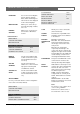
Main Menu History Switch to playback view View Settings Time and Date System Settings Bosch Security Systems | 2003-06 Sequence Alarms Aux - Output Recorder Installation Service System Settings Hour Format Time Date Format Date Time and Date PIP Position Hide Titles Hide Time/Date Brightness Contrast Color Sharpness Hue (NTSC only) Cancel View Settings History list History System Diagnose Factory Defaults Service Setup Camera 4 ------------------- Language Beep Volume External Control Setup Cam
VSS7390/01T Switcher | Installation Manual | Chapter 3 3 EN | 12 TECHNICAL SPECIFICATIONS APPROVALS Safety Europe EN60065 USA UL6500 UL & cUL listed Australia C-Tick Electro Magnetic Compatibility (EMC) Audio input RCA (0.5 Vpp, input impedance 10 kOhm) Video output BNC (1 Vpp, output impedance 75 Ohm) Audio output RCA (0.
Bosch Sicherheitssysteme GmbH Bosch Security Systems B.V. Ludwig-Bölkow-Allee P.O. Box 80002 85521 Ottobrunn 5600 JB Eindhoven Germany The Netherlands www.bosch-sicherheitssysteme.de www.boschsecuritysystems.com 3122 165 22352 03-30 © 2003 Bosch Security Systems B.V.