
Installation Manual


Installation | 15US
6 720 646 951 (2011/09)Copyright
US wiring
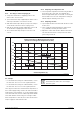
• The minimum recommended wire size is 8 AWG. (The
terminal block will accept cables up to 6 AWG size).
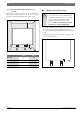
• The cable entry is via the 1¼ inch cable entry hole on
the bottom right hand edge of the back plate.
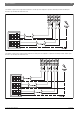
• Strip back the insulation on the power wires about
½ inch. Connect the live wires to the terminals
marked “L1” and “L2.” There are two pairs of live
wires in the WH17 and three pairs of live wires in the
WH27. (See Fig. 7 and Fig. 8, page 16).
• Any insulation on the ground wires should be stripped
back about ¾ inch. The ground leads must be
connected to the pillar terminal marked “GR”. (See
Fig. 7 and Fig. 8, page 16).
• Make sure the terminal block screws are tightened
securely. Loose connections can cause wires to heat
up.
• Make sure that the ground wires are wrapped around
its terminal stud and into the saddle washer. The nut
should be tightened securely.
• Attach the front cover and tighten the retaining
screws.
As per the Canadian Electrical Code, C22.1-
02 Section 26-744, an auxiliary terminal
block must be fitted to the heater before
connecting to the electrical supply. This is
available as a kit from Bosch
Thermotechnology Corp. Part Number “AE
Canada Kit”. (Contact 800-798-8161).