INSTALLATION AND MAINTENANCE INSTRUCTIONS TWIN COIL INDIRECT UNVENTED HOT WATER CYLINDER GREENSTORE TC CYLINDER SERIES 6 720 645 752 (2012/05) UK (T30.41634.02) 6 720 645 525-00.
CONTENTS CONTENTS 1 Key to symbols and safety precautions . . . . . . . . . . . . . . . . . . . 3 1.1 Explanation of symbols . . . . . . . . . . . . . . . . . . . . . . . . . . . 3 1.2 Safety instructions . . . . . . . . . . . . . . . . . . . . . . . . . . . . . . 3 2 Product details . . . . . . . . . . . . . . . . . . . . . . . . . . . . . . . . . . . . . . . . 4 2.1 Usage . . . . . . . . . . . . . . . . . . . . . . . . . . . . . . . . . . . . . . . . . 4 2.2 Intended use . . . . . . . . . . . . . . .
KEY TO SYMBOLS AND SAFETY PRECAUTIONS 1 KEY TO SYMBOLS AND SAFETY PRECAUTIONS 1.1 EXPLANATION OF SYMBOLS WARNING SYMBOLS Safety instructions in this document are framed and identified by a warning triangle which is printed on a grey background. Electrical hazards are identified by a lightning symbol surrounded by a warning triangle. Signal words indicate the seriousness of the hazard in terms of the consequences of not following the safety instructions.
PRODUCT DETAILS 2 PRODUCT DETAILS 2.1 USAGE These cylinders are designed to accept input from two heat sources, the most common being a solar input supported by a controlled appliance such as a gas or oil boiler. The maximum cylinder heat input must not exceed the following values: Cylinder TC-150 TC-180 TC-210 TC-250 TC-300 Max. cylinder heat input 31.9 kW 39.
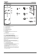
PRODUCT DETAILS STANDARD DELIVERY 4 AQU-16-3W 1 6 AQU-31-3W 2.4 AQUA-15-3W 9 2 AQU-17-3W 3 5 7 AQ U-1 9- 3W 3W -21- AQU-18-3W U AQ 8 10 11 6 720 645 525-07.2O Fig.
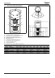
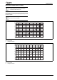
PRODUCT DETAILS 2.7 PHYSICAL AND CONNECTION DIMENSIONS 5 6 7 7 4 3 8 2 2 15° 25° 35° 45° 45° J 9 10 10 Cylinder TC-150 TC-180 TC-210 TC-250 TC-300 Customer order part numbers 7 716 800 542 7 716 800 543 7 716 800 544 7 716 800 545 7 716 800 546 A/mm 349.5 349.5 424.5 424.5 424.5 B/mm 404.5 404.5 479.5 479.5 479.5 C/mm 449.5 449.5 524.5 524.5 524.5 Fig. 3 D/mm 724 724 1028 1112 1112 E C A D F G Overview of connections Sensor pocket, bottom (internal Ø 20.
PRODUCT DETAILS 50 CLEARANCE DIMENSIONS 50 6 720 645 525-06.1O 180 80 50 Fig.
PRODUCT DETAILS 2.8 SPECIFICATION Cylinder type Greenstore WRAS No. WRc No.
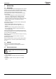
PRODUCT DETAILS PRESSURE DROP, INTERNAL INDIRECT COIL (IN BAR) When calculating the pressure drop in the solar circuit: B Take the influence of the antifreeze used and the manufacturer's details into account. Example: With a water/propylene-glycol mixture of 55/45 (frost protection down to approximately – 30 °C), the pressure drop is approximately 1.3 times the value for tap water. Pressure drop values resulting from the mains are not taken into account in the diagram.
INSTALLATION 3 INSTALLATION 3.1 REGULATIONS This System has been approved to the Building Regulations for unvented hot water storage systems and the Local Authority must be notified of the intention to install. Therefore the installation must be carried out by a person competent to install unvented hot water systems. The installation must be carried out in accordance with the following recommendations: • All current Building Regulations issued by the Department of the Environment, i.e.
INSTALLATION 3.4 SOLAR CONNECTION DIAGRAM T1 TDS WW HP 230V AC TWM FK SV1 SP GSP SWC TB 230V AC 5 M MAG SF ICS SV2 M T2 RV E S...solar DM RV RE 6 720 645 525-03.1O KW Fig. 7 DM E FK GSP HP ICS KW MAG RE RV SF SP SV1 SV2 SWC S...
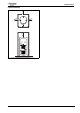
INSTALLATION 3.5 INSTALLING THE TEMPERATURE SENSORS The temperature sensors and safety equipment are fitted in different locations on the cylinder, subject to system. 3 2 1 6 720 645 525-05.1O Fig.
INSTALLATION 3.6 INSTALLATION All hydraulic cylinder connections are suitable for 22 mm pipes. B Make connections with the compression fittings supplied. 3.6.1 CONNECTION OF THE SECONDARY APPLIANCE B Connect to the upper coil (Æ fig. 2 [2], page 6) using the compression fittings supplied, either connection can be flow or return, performance is identical either way. The heating circuit must be positively pumped as gravity circulation is not possible.
INSTALLATION 3.6.5 DHW EXPANSION VESSEL B Connect the expansion vessel using the hose supplied to the cold water inlet control group. For DHW systems with a large volume: B Check whether the expansion vessel supplied (18 or 25 litres) is adequate and if required, install an additional expansion vessel in parallel to the one supplied, ensuring the air charge of each is identical. WARNING: Risk of scalding! Hot water can lead to severe scalding.
INSTALLATION The table below is based on copper tube. Plastic pipes may be of different bore and resistance. Sizes and maximum lengths of plastic should be calculated using data prepared for the type of pipe being used. Valve outlet size G1/2 G3/4 G1 Maximum resistance allowed, expressed as a Minimum size of discharge Minimum size of discharge length of straight pipe pipe D11) pipe D21) from tundish (i. e.
INSTALLATION 3.7 ELECTRICAL CONNECTIONS DANGER: Risk of electric shock! B Before making any electrical connections, disconnect the power supply (230 V AC) to the heating system. B Make sure all terminal screws are properly tightened before commissioning especially on immersion heater line. CONNECTING THE INDIRECT CONTROLS The indirect thermal controls should be wired into a suitable indirect control system to ensure optimum control of the cylinder and boiler.
INSTALLATION 6 720 645 525-10.1WO Fig. 11 Variant dual thermostat wiring: wiring diagram 3 port mid position valve (Y-plan) + 2 port valve G3 protection from excessive solar input. G3 protection from excessive solar input. A solar high limit thermostat will isolate the solar controller and solar pump. Additional wiring for solar pump stations without a gravity break check valve. The solar pump station MUST incorporate a gravity break check valve.
INSTALLATION CONNECTING THE IMMERSION HEATER (HEATERS CONFORM TO EN60335.2.73) B Ensure the mains voltage corresponds to the voltage rating of the heater as shown on the rating label on the terminal cover. B Only use rigid wires 1.5 mm2 for main supply. Flexible wire may cause poor electrical connection to the heater, resulting in overheat. B When connecting the thermostat please ensure the male pins are securely located within the female sockets.
COMMISSIONING 5 2 NOTICE: B When draining either the domestic hot water system or the cylinder ensure the cold water supply is isolated and that at least two hot water draw off points are opened. One of these hot water draw off points must be the one closest to the cylinder in height terms. The drain valve installed at the cold water supply inlet to the cylinder should be used, where practicable. 1 AQU-35-3W 3 5.1 Fig.
INSPECTION/MAINTENANCE 7 INSPECTION/MAINTENANCE 7.1 RECOMMENDATIONS FOR USERS B Arrange a maintenance and inspection contract with a competent person. Have the heating appliance and the DHW cylinder serviced annually. CAUTION: A safety valve malfunction can result in excessive pressure levels. B Check the function of the expansion relief valve in the cold water inlet control group and the temperature and pressure relief valve, and flush several times by cracking them open. 7.
MAINS PRESSURE HOT WATER STORAGE SYSTEM COMMISSIONING CHECKLIST This Commissioning Checklist is to be completed in full by the competent person who commissioned the storage system as a means of demonstrating compliance with the appropriate Building Regulations and then handed to the customer to keep for future reference. Failure to install and commission this equipment to the manufacturer’s instructions may invalidate the warranty but does not affect statutory rights.
Service Record It is recommended that your heating system is serviced regularly and that the appropriate Service Interval Record is completed. Service Provider Before completing the appropriate Service Record below, please ensure you have carried out the service as described in the manufacturer’s instructions. Always use the manufacturer’s specified spare part when replacing controls. Service 1 Date: Service 2 Date: Engineer Name: Engineer Name: Company Name: Company Name: Telephone No.
6 720 645 752 (2012/05) 23
WORCESTER, BOSCH GROUP: Worcester, Bosch Group Cotswold Way, Warndon, Worcester WR4 9SW. Tel. 0844 892 9900 Worcester, Bosch Group is a brand name of Bosch Thermotechnology Ltd. worcester-bosch.co.