
Install Instructions
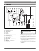

Table Of Contents
- Contents
- 1 Key to symbols and safety instructions
- 1.1 Key to symbols
- 1.2 General safety instructions
- 2 Scope of delivery
- 3 Information about the appliance
- 3.1 Proper use
- 3.2 Overview of boiler types
- 3.3 Rating plate
- 3.4 Appliance description
- 3.5 Accessories
- 3.6 Product dimensions and minimum clearances
- 3.7 Appliance layout heating boiler ZBR..-3A
- 3.8 Appliance layout combi boiler ZWB..-3A
- 3.9 Electrical wiring heating boiler ZBR..-3A
- 3.10 Electrical wiring combi boiler ZWB..-3A
- 3.11 Technical data heating boiler ZBR16-3A...
- 3.12 Technical data heating boiler ZBR21-3A...
- 3.13 Technical data heating boiler ZBR28-3A...
- 3.14 Technical data heating boiler ZBR35-3A...
- 3.15 Technical data heating boiler ZBR42-3A...
- 3.16 Technical data combi boiler ZWB28-3A...
- 3.17 Technical data combi boiler ZWB35-3A...
- 3.18 Technical data combi boiler ZWB42-3A...
- 3.19 Condensate composition
- 4 Regulations
- 5 Common Applications of ZBR boilers
- 6 Installation
- 6.1 Notes on installation and operation
- 6.1.1 Notes on installation and operation
- Fill and make-up water for the heating system
- Recommended steps for commissioning a new or retrofit boiler installation
- Recirculation pump/DHW recirculation lines
- Open vented heating systems
- Gravity heating systems
- Galvanized radiators or pipes.
- Plastic pipework
- Use of a room temperature control
- Primary-secondary piping or a low loss header
- Water Chemistry Guidelines
- Corrosion inhibitors
- Boiler sealer
- LPG
- 6.1.2 Other important information
- 6.1.1 Notes on installation and operation
- 6.2 Comparing the size of the integrated expansion vessel
- 6.3 ZBR..-3A appliances (heating boilers): Selecting an expansion vessel
- 6.4 Selecting the installation location
- 6.5 Pre-installing pipes
- 6.6 Mounting the appliance
- 6.7 Installing a low water cut off (LWCO)
- 6.8 Connecting flue gas accessories
- 6.9 Testing gas and water connections for leaks
- 6.1 Notes on installation and operation
- 7 Making the electrical connections
- 7.1 General notes
- 7.2 Low voltage electrical connections in the Heatronic boiler control
- 7.3 Electrical connections in the junction box (120 VAC)
- 7.4 Connecting the LWCO device
- 8 Commissioning
- 8.1 Before operating the appliance
- 8.2 Switching the appliance ON/OFF
- 8.3 Setting up space heating
- 8.4 Programming the FW 200 heating control unit
- 8.5 FW 200 heating control quick start
- 8.6 After commissioning
- 8.7 ZBR..-3A appliances (heating boilers) with DHW tank: Setting the DHW temperature
- 8.8 ZWB..-3A appliances (combi boilers): Setting the DHW temperature
- 8.9 Setting manual summer mode
- 8.10 Setting frost protection
- 8.11 Activating the key pad lock
- 9 ZBR..-3A appliances (heating boiler) with DHW tank: Thermal disinfection
- 10 Boiler circulator
- 11 Heatronic boiler control settings
- 11.1 Guideline to service functions
- 11.2 Overview of the service functions
- 11.3 Description of the service functions
- 11.3.1 First service level
- Service function 1.A: Maximum space heating output
- Service function 1.b: Maximum DHW output
- Service function 1.E: Pump mode for space heating operation
- Service function 1. F: Pump mode (only heating boiler ZBR..-3A)
- Service function 2.A: Heating circuit pump lockout time (only heating boiler ZBR..-3A)
- Service function 2.b: Maximum supply temperature
- Service function 2.C: Purging function
- Service function 2.d: Thermal disinfection (legionella protection)
- Service function 2.F: Operating mode
- Service function 3.A: Automatic anti-cycle function
- Service function 3.b: Set anti-cycle time
- Service function 3.C: Switching differential
- Service function 3.d: Minimum output (heating and DHW)
- Service function 3.E: Cycle time, keeping DHW hot (only combi boiler ZWB..-3A)
- Service function 3.F: Constant DHW period (only combi boiler ZWB..-3A)
- Service function 4.b: Maximum heat exchanger temperature (only combi boiler ZWB..-3A)
- Service function 4.d: Audible fault warning tone
- Service function 4.E: Appliance type
- Service function 4.F: Condensate trap filling sequence
- Service function 5.A: Reset inspection interval
- Service function 5.b: Fan post purge time
- Service function 5.E: Functionality of black plug in boiler junction box
- Service function 5.F: Set inspection interval
- Service function 6.A: Display the latest fault code
- Service function 6.b: Room temperature control, current voltage, terminal 2
- Service function 6.C: Supply temperature required by outdoor reset control
- Service function 6.d: Current DHW turbine flow rate (only combi boiler ZWB..-3A)
- Service function 7.A: Indicator lamp for burner operation / faults
- Service function 7.b: 3-way valve in center position
- Service function 7.d: Connecting an external supply or low-loss header temperature sensor
- Service function 7.E: Building drying function
- Service function 0.A: Do not use this setting!
- Service function 0.d: Altitude adjustment
- Service function 0.E: Metric or US customary units
- 11.3.2 Second service level
- Service function 8.A: Software version
- Service function 8.b: Code plug number
- Service function 8.C: GFA Gas burner control unit status
- Service function 8.d: GFA Gas burner control unit fault
- Service function 8.E: Restore boiler to factory settings
- Service function 8.F: Permanent ignition
- Service function 9.A: Constant mode
- Service function 9.b: Current fan speed
- Service function 9.C: Current boiler output
- Service function 9.d: Set fan start speed
- Service function 9.E: Turbine signal delay (only combi boiler ZWB..-3A)
- Service function 9.F: Heating zone pump post purge
- Service function A.b: Display DHW temperature
- Service function A.C: Display DHW tank temperature
- Service function b.F: Solar DHW backup heating delay (only combi boiler ZWB..-3A)
- Service function C.d: Display current heat demand
- 11.3.1 First service level
- 12 Gas type conversion
- 13 Flue gas test
- 14 Environmental responsibility/disposal
- 15 Inspection and maintenance
- Heat exchanger
- Heatronic boiler control
- Notes on installation and operation
- After the inspection/maintenance
- 15.1 Description of various steps
- 15.1.1 Calling up the latest fault (service function 6.A)
- 15.1.2 Fresh water filter (only combi boiler ZWB..-3A)
- 15.1.3 Plate type heat exchanger (only combi boiler ZWB..-3A)
- 15.1.4 Checking the electrodes
- 15.1.5 Burner servicing
- 15.1.6 Heat exchanger block inspection and cleaning
- 15.1.7 Condensate trap cleaning
- 15.1.8 Checking the mixer diaphragm
- 15.1.9 Expansion vessel
- 15.1.10 Setting the boiler water pressure
- 15.1.11 Testing system water quality
- 15.1.12 Inspecting electrical wiring
- 15.2 Checklist for inspection and maintenance
- 16 Readings on the display
- 17 Faults
- 18 Commissioning log for the appliance
- 19 Spare parts
- Index

60 | Heatronic boiler control settings
Greenstar6 720 806 992 (2013/09)
Service function 2.A: Heating circuit pump lockout time (only
heating boiler ZBR..-3A)
During the runtime of an external 3-way valve actuator, the space
heating pump is blocked. Select the run time of the 3-way valve actuator
between 01 - 24 (10 - 240) seconds according to the manufacturer's
documentation.
Default setting is 24 (240 seconds).
Service function 2.b: Maximum supply temperature
The values of this service function displayed depend on the setting of the
service function 0.E:
Service function 0.E is set to 00 (metric units):
• The maximum supply temperature can be adjusted between 35 and
88 (35 - 88 °C).
Service function 0.E is set to 01 (US customary units):
• The maximum supply temperature can be adjusted between 96 and
190 (96 - 190 °F).
Default setting is 190 (190 °F (88 °C)).
Service function 2.C: Purging function
The following settings are possible:
• 00: Purging function off
• 01: Purging function is switched on and after completion
automatically reset to 00
• 02: Purging function is permanently on and is not reset to 00
Default setting is 00 for heating boilers ZBR..-3A appliances, otherwise
01.
Service function 2.d: Thermal disinfection (legionella protection)
When this service function is enabled, the DHW is permanently heated
to approx. 158 °F (70 °C) if the DHW temperature dial has been turned
clockwise to max.
The following settings are possible:
• 00: Thermal disinfection not enabled
• 01: Thermal disinfection enabled
Default setting is 00 (disabled).
Service function 2.F: Operating mode
With this service function, you can temporarily change the appliance's
operating mode.
The following settings are possible:
• 00: Default mode; the appliance runs according to control settings.
• 01: The appliance runs for 15 minutes at minimum output. The
display shows 2.F. When this service function is aborted or has been
active for 15 minutes, the appliance reverts to default mode.
• 02: The appliance runs for 15 minutes at maximum output. The
display shows 2.F. When this service function is aborted or has been
active for 15 minutes, the appliance reverts to default mode.
Default setting is 00.
Service function 3.A: Automatic anti-cycle function
Use service function 3.A to set the automatic adaptation of the anti-cycle
time. This can be required in case of unfavorably-dimensioned heating
systems. Short cycling may increase boiler and system wear and tear,
increase emissions, reduce comfort, and should be avoided.
With auto-adaptation of the anti-cycle time disabled, the anti-cycle time
must be set using service function 3.b ( page 61).
The following settings are available:
• 00: Automatic adaptation of the anti-cycle time is disabled
• 01: Automatic adaptation of the anti-cycle time is enabled
Default setting is 00 (switched off).
NOTICE: System damage or boiler malfunction!
▶ Never change the setting of this service function on
combi boiler ZWB..-3A appliances.
This setting is only active if Service function
1. F: Pump mode is set to 01 (3-way valve).
When the appliance is switched ON for the first time, it
performs a once-only purging sequence. This involves
the heating zone pump switching on and off at intervals
(for approx. 4 minutes).
The display shows in alternation with the supply
temperature.
This service function allows activating the purging
function manually, e.g. after servicing.
WARNING: Risk of scalding!
Hot water can result in severe scalding.
▶ Carry out thermal disinfection only outside the normal
hours of use.
▶ Install a tempering valve if this function is enabled
permanently.
If an outdoor reset control is connected, there is no need
to adjust this setting on the appliance.
The control automatically optimizes the anti-cycle time.