
Operating instructions


Commissioning | 35
6 720 644 143 (2010/09)
8 Commissioning
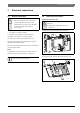
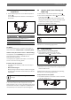
Fig. 33
1 Flow temperature control
2 DHW temperature control
3 Chimney sweep button
4 Service button
5 Burner ON indicator
6 Main switch
7 Automatic air vent valve
8 Display
9 Pressure gauge
10 reset button
11 eco button
12 Holiday button
13 Drain from pressure relief valve (heating circuit)
14 Gas tap
15 CH return isolator
16 Filling loop (ZWB)
17 Cold water tap (ZWB),
cylinder return (ZSB)
18 DHW connection (ZWB),
cylinder flow (ZSB)
19 CH flow isolator
20 Condensate hose
6 720 644 143-17.1O
1819
reset
10
11
12
eco
15161714
4
3
2
5
1
6
8
7
9
20
13