
Install Instructions

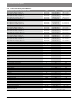

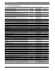

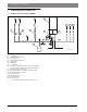
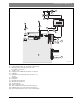
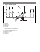
Table Of Contents
- Contents
- 1 Key to symbols and safety instructions
- 1.1 Key to symbols
- 1.2 General safety instructions
- 2 Scope of delivery
- 3 Information about the appliance
- 3.1 Proper use
- 3.2 Overview of boiler types
- 3.3 Rating plate
- 3.4 Appliance description
- 3.5 Accessories
- 3.6 Product dimensions and minimum clearances
- 3.7 Appliance layout heating boiler ZBR..-3A
- 3.8 Appliance layout combi boiler ZWB..-3A
- 3.9 Electrical wiring heating boiler ZBR..-3A
- 3.10 Electrical wiring combi boiler ZWB..-3A
- 3.11 Technical data heating boiler ZBR16-3A...
- 3.12 Technical data heating boiler ZBR21-3A...
- 3.13 Technical data heating boiler ZBR28-3A...
- 3.14 Technical data heating boiler ZBR35-3A...
- 3.15 Technical data heating boiler ZBR42-3A...
- 3.16 Technical data combi boiler ZWB28-3A...
- 3.17 Technical data combi boiler ZWB35-3A...
- 3.18 Technical data combi boiler ZWB42-3A...
- 3.19 Condensate composition
- 4 Regulations
- 5 Common Applications of ZBR boilers
- 6 Installation
- 6.1 Notes on installation and operation
- 6.1.1 Notes on installation and operation
- Fill and make-up water for the heating system
- Recommended steps for commissioning a new or retrofit boiler installation
- Recirculation pump/DHW recirculation lines
- Open vented heating systems
- Gravity heating systems
- Galvanized radiators or pipes.
- Plastic pipework
- Use of a room temperature control
- Primary-secondary piping or a low loss header
- Water Chemistry Guidelines
- Corrosion inhibitors
- Boiler sealer
- LPG
- 6.1.2 Other important information
- 6.1.1 Notes on installation and operation
- 6.2 Comparing the size of the integrated expansion vessel
- 6.3 ZBR..-3A appliances (heating boilers): Selecting an expansion vessel
- 6.4 Selecting the installation location
- 6.5 Pre-installing pipes
- 6.6 Mounting the appliance
- 6.7 Installing a low water cut off (LWCO)
- 6.8 Connecting flue gas accessories
- 6.9 Testing gas and water connections for leaks
- 6.1 Notes on installation and operation
- 7 Making the electrical connections
- 7.1 General notes
- 7.2 Low voltage electrical connections in the Heatronic boiler control
- 7.3 Electrical connections in the junction box (120 VAC)
- 7.4 Connecting the LWCO device
- 8 Commissioning
- 8.1 Before operating the appliance
- 8.2 Switching the appliance ON/OFF
- 8.3 Setting up space heating
- 8.4 Programming the FW 200 heating control unit
- 8.5 FW 200 heating control quick start
- 8.6 After commissioning
- 8.7 ZBR..-3A appliances (heating boilers) with DHW tank: Setting the DHW temperature
- 8.8 ZWB..-3A appliances (combi boilers): Setting the DHW temperature
- 8.9 Setting manual summer mode
- 8.10 Setting frost protection
- 8.11 Activating the key pad lock
- 9 ZBR..-3A appliances (heating boiler) with DHW tank: Thermal disinfection
- 10 Boiler circulator
- 11 Heatronic boiler control settings
- 11.1 Guideline to service functions
- 11.2 Overview of the service functions
- 11.3 Description of the service functions
- 11.3.1 First service level
- Service function 1.A: Maximum space heating output
- Service function 1.b: Maximum DHW output
- Service function 1.E: Pump mode for space heating operation
- Service function 1. F: Pump mode (only heating boiler ZBR..-3A)
- Service function 2.A: Heating circuit pump lockout time (only heating boiler ZBR..-3A)
- Service function 2.b: Maximum supply temperature
- Service function 2.C: Purging function
- Service function 2.d: Thermal disinfection (legionella protection)
- Service function 2.F: Operating mode
- Service function 3.A: Automatic anti-cycle function
- Service function 3.b: Set anti-cycle time
- Service function 3.C: Switching differential
- Service function 3.d: Minimum output (heating and DHW)
- Service function 3.E: Cycle time, keeping DHW hot (only combi boiler ZWB..-3A)
- Service function 3.F: Constant DHW period (only combi boiler ZWB..-3A)
- Service function 4.b: Maximum heat exchanger temperature (only combi boiler ZWB..-3A)
- Service function 4.d: Audible fault warning tone
- Service function 4.E: Appliance type
- Service function 4.F: Condensate trap filling sequence
- Service function 5.A: Reset inspection interval
- Service function 5.b: Fan post purge time
- Service function 5.E: Functionality of black plug in boiler junction box
- Service function 5.F: Set inspection interval
- Service function 6.A: Display the latest fault code
- Service function 6.b: Room temperature control, current voltage, terminal 2
- Service function 6.C: Supply temperature required by outdoor reset control
- Service function 6.d: Current DHW turbine flow rate (only combi boiler ZWB..-3A)
- Service function 7.A: Indicator lamp for burner operation / faults
- Service function 7.b: 3-way valve in center position
- Service function 7.d: Connecting an external supply or low-loss header temperature sensor
- Service function 7.E: Building drying function
- Service function 0.A: Do not use this setting!
- Service function 0.d: Altitude adjustment
- Service function 0.E: Metric or US customary units
- 11.3.2 Second service level
- Service function 8.A: Software version
- Service function 8.b: Code plug number
- Service function 8.C: GFA Gas burner control unit status
- Service function 8.d: GFA Gas burner control unit fault
- Service function 8.E: Restore boiler to factory settings
- Service function 8.F: Permanent ignition
- Service function 9.A: Constant mode
- Service function 9.b: Current fan speed
- Service function 9.C: Current boiler output
- Service function 9.d: Set fan start speed
- Service function 9.E: Turbine signal delay (only combi boiler ZWB..-3A)
- Service function 9.F: Heating zone pump post purge
- Service function A.b: Display DHW temperature
- Service function A.C: Display DHW tank temperature
- Service function b.F: Solar DHW backup heating delay (only combi boiler ZWB..-3A)
- Service function C.d: Display current heat demand
- 11.3.1 First service level
- 12 Gas type conversion
- 13 Flue gas test
- 14 Environmental responsibility/disposal
- 15 Inspection and maintenance
- Heat exchanger
- Heatronic boiler control
- Notes on installation and operation
- After the inspection/maintenance
- 15.1 Description of various steps
- 15.1.1 Calling up the latest fault (service function 6.A)
- 15.1.2 Fresh water filter (only combi boiler ZWB..-3A)
- 15.1.3 Plate type heat exchanger (only combi boiler ZWB..-3A)
- 15.1.4 Checking the electrodes
- 15.1.5 Burner servicing
- 15.1.6 Heat exchanger block inspection and cleaning
- 15.1.7 Condensate trap cleaning
- 15.1.8 Checking the mixer diaphragm
- 15.1.9 Expansion vessel
- 15.1.10 Setting the boiler water pressure
- 15.1.11 Testing system water quality
- 15.1.12 Inspecting electrical wiring
- 15.2 Checklist for inspection and maintenance
- 16 Readings on the display
- 17 Faults
- 18 Commissioning log for the appliance
- 19 Spare parts
- Index

22 | Information about the appliance
Greenstar6 720 806 992 (2013/09)
3.15 Technical data heating boiler ZBR42-3A...
Input/Output at elevation 0 - 2000 feet (0 - 610 m) Unit NG LPG (propane)
Max. input rate 180/79 °F (82/26 °C) BTU/hr (kW) 151,600 (44.4) 148,300 (43.5)
Max. output rate 104/86 °F (40/30 °C) BTU/hr (kW) 137,500 (40.3) 137,500 (40.3)
Max. output rate 122/86 °F (50/30 °C) BTU/hr (kW) 137,500 (40.3) 137,500 (40.3)
Max. output rate 176/140 °F (80/60 °C) BTU/hr (kW) 134,400 (39.4) 134,400 (39.4)
Min. input rate 180/79 °F (82/26 °C) BTU/hr (kW) 36,000 (10.5) 46,400 (13.6)
Min. output rate 104/86 °F (40/30 °C) BTU/hr (kW) 35,500 (10.4) 46,400 (13.6)
Min. output rate 122/86 °F (50/30 °C) BTU/hr (kW) 35,100 (10.3) 46,100 (13.5)
Min. output rate 176/140 °F (80/60 °C) BTU/hr (kW) 31,700 (9.3) 42,000 (12.3)
Input/Output at elevation 2000 - 4500 feet (611 - 1372 m) above sea level
Max. input rate 180/79 °F (82/26 °C) BTU/hr (kW) 136,440 (40.0) 139,402 (40.9)
Max. output rate 104/86 °F (40/30 °C) BTU/hr (kW) 123,750 (36.3) 129,250 (37.9)
Max. output rate 122/86 °F (50/30 °C) BTU/hr (kW) 123,750 (36.3) 129,250 (37.9)
Max. output rate 176/140 °F (80/60 °C) BTU/hr (kW) 120,960 (35.5) 126,336 (37.0)
Input/Output at elevation 4500 - 7000 feet (1373 - 2134 m) above sea level
Max. input rate 180/79 °F (82/26 °C) BTU/hr (kW) 125,828 (36.9) 129,021 (37.8)
Max. output rate 104/86 °F (40/30 °C) BTU/hr (kW) 114,125 (33.5) 119,625 (35.1)
Max. output rate 122/86 °F (50/30 °C) BTU/hr (kW) 114,125 (33.5) 119,625 (35.1)
Max. output rate 176/140 °F (80/60 °C) BTU/hr (kW) 111,552 (32.7) 116,928 (34.3)
Gas connection value
Natural Gas – H
s
= 1,010 BTU/ft
3
(37.3MJ/m
3
)ft
3
/hr (m
3
/h) 149 (4.2) –
Liquid Propane Gas – HD-S = 2,500 BTU/ft3 (93.1MJ/m3) ft
3
/hr (m
3
/h) – 59 (1.7)
Permissible inlet gas pressure
NG in. W.C. (mbar) 3.5-10.5" (8.7-26.1) –
LPG (propane) in. W.C. (mbar) – 8-13" (19.9-32.3)
Flue gas
Flue gas mass flow at maximum/minimum nominal output gps 18.0/4.5 17.5/5.6
Flue gas temperature 176/140 °F (80/60 °C) at maximum/minimum nominal heat
input
°F ( °C)
171/135 (77/57) 171/135 (77/57)
Flue gas temperature 104/86 °F (40/30 °C) at maximum/minimum nominal heat
input
°F ( °C)
133/91 (56/33) 133/91 (56/33)
CO
2
at max. nominal output % 9.4 11.0
CO
2
at minimum nominal output % 8.6 10.4
Condensate
Max. condensate quantity (t
R
= 86 °F (30 °C)) gph (l/h) 0.9 (3.5) 0.9 (3.5)
pH level, approx. 4.8 4.8
General
Voltage VAC 120 120
Frequency Hz 60 60
Max. power consumption (central heating mode) W 205 205
Max. power consumption (Stand-by) W < 6 < 6
Sound pressure level
dB(A)
45 45
Max. supply temperature °F ( °C) 190 (88) 190 (88)
Max. permissible operating pressure (P
MS
) heating psi (bar) 30 (2.07) 30 (2.07)
Permissible ambient temperature °F ( °C) 32 - 122 (0 - 50) 32 - 122 (0 - 50)
Nominal water capacity (heating) Gal (L) 0.925 (3.5) 0.925 (3.5)
Weight (without packaging) lbs. (kg) 103.6 (47) 103.6 (47)
Dimensions, W x H x D
inch
(mm)
17-21/64" × 33-15/32" × 13-57/64"
(440 × 850 × 353)
Table 7 Technical data heating boiler ZBR42-3A...