
Install Instructions
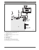
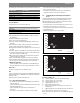
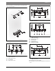
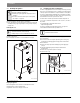
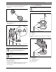
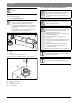
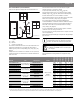
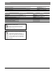
Table Of Contents
- Contents
- 1 Key to symbols and safety instructions
- 1.1 Key to symbols
- 1.2 General safety instructions
- 2 Scope of delivery
- 3 Information about the appliance
- 3.1 Proper use
- 3.2 Overview of boiler types
- 3.3 Rating plate
- 3.4 Appliance description
- 3.5 Accessories
- 3.6 Product dimensions and minimum clearances
- 3.7 Appliance layout heating boiler ZBR..-3A
- 3.8 Appliance layout combi boiler ZWB..-3A
- 3.9 Electrical wiring heating boiler ZBR..-3A
- 3.10 Electrical wiring combi boiler ZWB..-3A
- 3.11 Technical data heating boiler ZBR16-3A...
- 3.12 Technical data heating boiler ZBR21-3A...
- 3.13 Technical data heating boiler ZBR28-3A...
- 3.14 Technical data heating boiler ZBR35-3A...
- 3.15 Technical data heating boiler ZBR42-3A...
- 3.16 Technical data combi boiler ZWB28-3A...
- 3.17 Technical data combi boiler ZWB35-3A...
- 3.18 Technical data combi boiler ZWB42-3A...
- 3.19 Condensate composition
- 4 Regulations
- 5 Common Applications of ZBR boilers
- 6 Installation
- 6.1 Notes on installation and operation
- 6.1.1 Notes on installation and operation
- Fill and make-up water for the heating system
- Recommended steps for commissioning a new or retrofit boiler installation
- Recirculation pump/DHW recirculation lines
- Open vented heating systems
- Gravity heating systems
- Galvanized radiators or pipes.
- Plastic pipework
- Use of a room temperature control
- Primary-secondary piping or a low loss header
- Water Chemistry Guidelines
- Corrosion inhibitors
- Boiler sealer
- LPG
- 6.1.2 Other important information
- 6.1.1 Notes on installation and operation
- 6.2 Comparing the size of the integrated expansion vessel
- 6.3 ZBR..-3A appliances (heating boilers): Selecting an expansion vessel
- 6.4 Selecting the installation location
- 6.5 Pre-installing pipes
- 6.6 Mounting the appliance
- 6.7 Installing a low water cut off (LWCO)
- 6.8 Connecting flue gas accessories
- 6.9 Testing gas and water connections for leaks
- 6.1 Notes on installation and operation
- 7 Making the electrical connections
- 7.1 General notes
- 7.2 Low voltage electrical connections in the Heatronic boiler control
- 7.3 Electrical connections in the junction box (120 VAC)
- 7.4 Connecting the LWCO device
- 8 Commissioning
- 8.1 Before operating the appliance
- 8.2 Switching the appliance ON/OFF
- 8.3 Setting up space heating
- 8.4 Programming the FW 200 heating control unit
- 8.5 FW 200 heating control quick start
- 8.6 After commissioning
- 8.7 ZBR..-3A appliances (heating boilers) with DHW tank: Setting the DHW temperature
- 8.8 ZWB..-3A appliances (combi boilers): Setting the DHW temperature
- 8.9 Setting manual summer mode
- 8.10 Setting frost protection
- 8.11 Activating the key pad lock
- 9 ZBR..-3A appliances (heating boiler) with DHW tank: Thermal disinfection
- 10 Boiler circulator
- 11 Heatronic boiler control settings
- 11.1 Guideline to service functions
- 11.2 Overview of the service functions
- 11.3 Description of the service functions
- 11.3.1 First service level
- Service function 1.A: Maximum space heating output
- Service function 1.b: Maximum DHW output
- Service function 1.E: Pump mode for space heating operation
- Service function 1. F: Pump mode (only heating boiler ZBR..-3A)
- Service function 2.A: Heating circuit pump lockout time (only heating boiler ZBR..-3A)
- Service function 2.b: Maximum supply temperature
- Service function 2.C: Purging function
- Service function 2.d: Thermal disinfection (legionella protection)
- Service function 2.F: Operating mode
- Service function 3.A: Automatic anti-cycle function
- Service function 3.b: Set anti-cycle time
- Service function 3.C: Switching differential
- Service function 3.d: Minimum output (heating and DHW)
- Service function 3.E: Cycle time, keeping DHW hot (only combi boiler ZWB..-3A)
- Service function 3.F: Constant DHW period (only combi boiler ZWB..-3A)
- Service function 4.b: Maximum heat exchanger temperature (only combi boiler ZWB..-3A)
- Service function 4.d: Audible fault warning tone
- Service function 4.E: Appliance type
- Service function 4.F: Condensate trap filling sequence
- Service function 5.A: Reset inspection interval
- Service function 5.b: Fan post purge time
- Service function 5.E: Functionality of black plug in boiler junction box
- Service function 5.F: Set inspection interval
- Service function 6.A: Display the latest fault code
- Service function 6.b: Room temperature control, current voltage, terminal 2
- Service function 6.C: Supply temperature required by outdoor reset control
- Service function 6.d: Current DHW turbine flow rate (only combi boiler ZWB..-3A)
- Service function 7.A: Indicator lamp for burner operation / faults
- Service function 7.b: 3-way valve in center position
- Service function 7.d: Connecting an external supply or low-loss header temperature sensor
- Service function 7.E: Building drying function
- Service function 0.A: Do not use this setting!
- Service function 0.d: Altitude adjustment
- Service function 0.E: Metric or US customary units
- 11.3.2 Second service level
- Service function 8.A: Software version
- Service function 8.b: Code plug number
- Service function 8.C: GFA Gas burner control unit status
- Service function 8.d: GFA Gas burner control unit fault
- Service function 8.E: Restore boiler to factory settings
- Service function 8.F: Permanent ignition
- Service function 9.A: Constant mode
- Service function 9.b: Current fan speed
- Service function 9.C: Current boiler output
- Service function 9.d: Set fan start speed
- Service function 9.E: Turbine signal delay (only combi boiler ZWB..-3A)
- Service function 9.F: Heating zone pump post purge
- Service function A.b: Display DHW temperature
- Service function A.C: Display DHW tank temperature
- Service function b.F: Solar DHW backup heating delay (only combi boiler ZWB..-3A)
- Service function C.d: Display current heat demand
- 11.3.1 First service level
- 12 Gas type conversion
- 13 Flue gas test
- 14 Environmental responsibility/disposal
- 15 Inspection and maintenance
- Heat exchanger
- Heatronic boiler control
- Notes on installation and operation
- After the inspection/maintenance
- 15.1 Description of various steps
- 15.1.1 Calling up the latest fault (service function 6.A)
- 15.1.2 Fresh water filter (only combi boiler ZWB..-3A)
- 15.1.3 Plate type heat exchanger (only combi boiler ZWB..-3A)
- 15.1.4 Checking the electrodes
- 15.1.5 Burner servicing
- 15.1.6 Heat exchanger block inspection and cleaning
- 15.1.7 Condensate trap cleaning
- 15.1.8 Checking the mixer diaphragm
- 15.1.9 Expansion vessel
- 15.1.10 Setting the boiler water pressure
- 15.1.11 Testing system water quality
- 15.1.12 Inspecting electrical wiring
- 15.2 Checklist for inspection and maintenance
- 16 Readings on the display
- 17 Faults
- 18 Commissioning log for the appliance
- 19 Spare parts
- Index

Installation | 33
6 720 806 992 (2013/09)Greenstar
The following anti-freeze fluids and concentrations have been approved:
Corrosion inhibitors
The following anti-corrosion agents are approved:
▶ System fluid pH must be maintained between 7 and 8.5 to prevent
system damage.
▶ Use only untreated water to fill the system.
▶ Do not use TSP (tri-sodium phosphate).
▶ Do not use fill water treated with salt bedding type exchangers (ion
exchanger).
▶ Never introduce non-approved boiler treatment or similar additives.
▶ Only use fill water with a hardness below 7 grains.
▶ Filling with chlorinated water is acceptable if chlorine levels are below
100 ppm.
▶ Do not use inhibitors or other additives unless listed in this document.
▶ Consult a local water treatment specialist for recommendations if any
of the above is outside the stated ranges.
▶ When using oxygen permeable PEX, the system must be separated
from the boiler by a heat exchanger.
▶ A correctly sized and working expansion vessel must be installed.
▶ Do not exceed the maximum permissible fl ow rate through the boiler.
Excessive flow can cause erosion damage to the heat exchanger.
▶ Eliminate System Leaks
Continuous addition of make-up water will constantly add oxygen to
the system and lead to corrosion. All system leaks must be repaired.
Boiler sealer
This boiler is not approved for use with boiler sealer.
LPG
To protect the appliance against high pressure (ANSI/Z223.1/NFPA54
(National fuel gas code) or CAN/CSA B 149.1 (Natural Gas and Propane
installation code)):
▶ Install a pressure regulator with a safety valve.
6.1.2 Other important information
• The installation of this boiler must comply with all national and local
code and regulations.
• Only operate this boiler with the combined air/flue system specifically
designed and approved for it.
• Only use approved venting systems per the manufacturer's
instructions.
• Do not dispose of untreated boiler condensate in septic systems.
• Inspect the sewer pipes for suitability before disposing of untreated
boiler condensate into them.
• Verify with the local authority that disposing of untreated boiler
condensate into public sewer systems is permitted.
6.2 Comparing the size of the integrated expansion
vessel
The following diagrams allow verifying that the integrated expansion
vessel has sufficient capacity for the intended application, or if an
additional expansion vessel is needed (not for radiant floor heating).
The following standard conditions were used:
• Precharge volume 20% of the rated volume in the expansion vessel
• Differential to the safety valve of 7.25 psi (0.5 bar)
• Precharge pressure of the expansion vessel equal to the static system
height above the boiler
• Maximum operating pressure: 30 psi (2.07 bar)
Fig. 13 Operating capacity of the expansion vessel in °F and gallons
Fig. 14 Operating capacity of the expansion vessel in °C and liters
Key to Fig. 13 and Fig. 14:
[I] Precharge pressure 7.25 psi (0.5 bar) (default setting)
[II] Precharge pressure 10.9 psi (0.75 bar)
[III] Precharge pressure 14.5 psi (1.0 bar)
t
V
Supply temperature in °F ( °C)
V
A
System capacity in gallons (liters)
A Within operating capacity of the expansion vessel (left of the
relevant curve)
B Additional expansion vessel required (right of the relevant curve)
▶ If results are borderline: Determine precise vessel sizes.
▶ If the results are to the right of the curve: Install additional expansion
vessel.
Chemical Name Concentration
Nalco (Varidos) FSK 22 - 55 %
Fernox Alphi 11 Observe manufacturer's instructions
Intercool NFP-50 AA 0 - 39 %
Antifrogen N Observe manufacturer's instructions
NoBurst AL 0 - 55 %
Table 14 Anti-freeze
Chemical Name Concentration
Fernox F1 Observe manufacturer's instructions
Nalco 77381 1 - 2 %
Sentinel X 100 1.1 %
Table 15 Corrosion inhibitors
200
80
100
120
140
160
180
0 20 40 80 100
120
60
t
V
/°F
V
A
/gal
6720641933-13.1O
A
B
I
III
II
90
30
40
50
60
70
80
0 75 150 300 375
450
225
t
V
/°C
V
A
/l
6720641933-27.1O
A
B
I
III
II