
Install Instructions
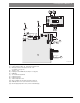
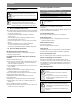
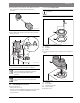
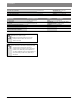
Table Of Contents
- Contents
- 1 Key to symbols and safety instructions
- 1.1 Key to symbols
- 1.2 General safety instructions
- 2 Scope of delivery
- 3 Information about the appliance
- 3.1 Proper use
- 3.2 Overview of boiler types
- 3.3 Rating plate
- 3.4 Appliance description
- 3.5 Accessories
- 3.6 Product dimensions and minimum clearances
- 3.7 Appliance layout heating boiler ZBR..-3A
- 3.8 Appliance layout combi boiler ZWB..-3A
- 3.9 Electrical wiring heating boiler ZBR..-3A
- 3.10 Electrical wiring combi boiler ZWB..-3A
- 3.11 Technical data heating boiler ZBR16-3A...
- 3.12 Technical data heating boiler ZBR21-3A...
- 3.13 Technical data heating boiler ZBR28-3A...
- 3.14 Technical data heating boiler ZBR35-3A...
- 3.15 Technical data heating boiler ZBR42-3A...
- 3.16 Technical data combi boiler ZWB28-3A...
- 3.17 Technical data combi boiler ZWB35-3A...
- 3.18 Technical data combi boiler ZWB42-3A...
- 3.19 Condensate composition
- 4 Regulations
- 5 Common Applications of ZBR boilers
- 6 Installation
- 6.1 Notes on installation and operation
- 6.1.1 Notes on installation and operation
- Fill and make-up water for the heating system
- Recommended steps for commissioning a new or retrofit boiler installation
- Recirculation pump/DHW recirculation lines
- Open vented heating systems
- Gravity heating systems
- Galvanized radiators or pipes.
- Plastic pipework
- Use of a room temperature control
- Primary-secondary piping or a low loss header
- Water Chemistry Guidelines
- Corrosion inhibitors
- Boiler sealer
- LPG
- 6.1.2 Other important information
- 6.1.1 Notes on installation and operation
- 6.2 Comparing the size of the integrated expansion vessel
- 6.3 ZBR..-3A appliances (heating boilers): Selecting an expansion vessel
- 6.4 Selecting the installation location
- 6.5 Pre-installing pipes
- 6.6 Mounting the appliance
- 6.7 Installing a low water cut off (LWCO)
- 6.8 Connecting flue gas accessories
- 6.9 Testing gas and water connections for leaks
- 6.1 Notes on installation and operation
- 7 Making the electrical connections
- 7.1 General notes
- 7.2 Low voltage electrical connections in the Heatronic boiler control
- 7.3 Electrical connections in the junction box (120 VAC)
- 7.4 Connecting the LWCO device
- 8 Commissioning
- 8.1 Before operating the appliance
- 8.2 Switching the appliance ON/OFF
- 8.3 Setting up space heating
- 8.4 Programming the FW 200 heating control unit
- 8.5 FW 200 heating control quick start
- 8.6 After commissioning
- 8.7 ZBR..-3A appliances (heating boilers) with DHW tank: Setting the DHW temperature
- 8.8 ZWB..-3A appliances (combi boilers): Setting the DHW temperature
- 8.9 Setting manual summer mode
- 8.10 Setting frost protection
- 8.11 Activating the key pad lock
- 9 ZBR..-3A appliances (heating boiler) with DHW tank: Thermal disinfection
- 10 Boiler circulator
- 11 Heatronic boiler control settings
- 11.1 Guideline to service functions
- 11.2 Overview of the service functions
- 11.3 Description of the service functions
- 11.3.1 First service level
- Service function 1.A: Maximum space heating output
- Service function 1.b: Maximum DHW output
- Service function 1.E: Pump mode for space heating operation
- Service function 1. F: Pump mode (only heating boiler ZBR..-3A)
- Service function 2.A: Heating circuit pump lockout time (only heating boiler ZBR..-3A)
- Service function 2.b: Maximum supply temperature
- Service function 2.C: Purging function
- Service function 2.d: Thermal disinfection (legionella protection)
- Service function 2.F: Operating mode
- Service function 3.A: Automatic anti-cycle function
- Service function 3.b: Set anti-cycle time
- Service function 3.C: Switching differential
- Service function 3.d: Minimum output (heating and DHW)
- Service function 3.E: Cycle time, keeping DHW hot (only combi boiler ZWB..-3A)
- Service function 3.F: Constant DHW period (only combi boiler ZWB..-3A)
- Service function 4.b: Maximum heat exchanger temperature (only combi boiler ZWB..-3A)
- Service function 4.d: Audible fault warning tone
- Service function 4.E: Appliance type
- Service function 4.F: Condensate trap filling sequence
- Service function 5.A: Reset inspection interval
- Service function 5.b: Fan post purge time
- Service function 5.E: Functionality of black plug in boiler junction box
- Service function 5.F: Set inspection interval
- Service function 6.A: Display the latest fault code
- Service function 6.b: Room temperature control, current voltage, terminal 2
- Service function 6.C: Supply temperature required by outdoor reset control
- Service function 6.d: Current DHW turbine flow rate (only combi boiler ZWB..-3A)
- Service function 7.A: Indicator lamp for burner operation / faults
- Service function 7.b: 3-way valve in center position
- Service function 7.d: Connecting an external supply or low-loss header temperature sensor
- Service function 7.E: Building drying function
- Service function 0.A: Do not use this setting!
- Service function 0.d: Altitude adjustment
- Service function 0.E: Metric or US customary units
- 11.3.2 Second service level
- Service function 8.A: Software version
- Service function 8.b: Code plug number
- Service function 8.C: GFA Gas burner control unit status
- Service function 8.d: GFA Gas burner control unit fault
- Service function 8.E: Restore boiler to factory settings
- Service function 8.F: Permanent ignition
- Service function 9.A: Constant mode
- Service function 9.b: Current fan speed
- Service function 9.C: Current boiler output
- Service function 9.d: Set fan start speed
- Service function 9.E: Turbine signal delay (only combi boiler ZWB..-3A)
- Service function 9.F: Heating zone pump post purge
- Service function A.b: Display DHW temperature
- Service function A.C: Display DHW tank temperature
- Service function b.F: Solar DHW backup heating delay (only combi boiler ZWB..-3A)
- Service function C.d: Display current heat demand
- 11.3.1 First service level
- 12 Gas type conversion
- 13 Flue gas test
- 14 Environmental responsibility/disposal
- 15 Inspection and maintenance
- Heat exchanger
- Heatronic boiler control
- Notes on installation and operation
- After the inspection/maintenance
- 15.1 Description of various steps
- 15.1.1 Calling up the latest fault (service function 6.A)
- 15.1.2 Fresh water filter (only combi boiler ZWB..-3A)
- 15.1.3 Plate type heat exchanger (only combi boiler ZWB..-3A)
- 15.1.4 Checking the electrodes
- 15.1.5 Burner servicing
- 15.1.6 Heat exchanger block inspection and cleaning
- 15.1.7 Condensate trap cleaning
- 15.1.8 Checking the mixer diaphragm
- 15.1.9 Expansion vessel
- 15.1.10 Setting the boiler water pressure
- 15.1.11 Testing system water quality
- 15.1.12 Inspecting electrical wiring
- 15.2 Checklist for inspection and maintenance
- 16 Readings on the display
- 17 Faults
- 18 Commissioning log for the appliance
- 19 Spare parts
- Index

38 | Installation
Greenstar6 720 806 992 (2013/09)
In case of open venting:
▶ Use basket on the air intake.
In case of concentric venting system:
Fig. 28 Horizontal venting system (telescopic concentric vent kit)
[1] Intake
[2] Exhaust
L 2 feet to 3 feet (610 mm to 915 mm)
▶ Install the concentric vent adaptor with the screws enclosed.
Fig. 29 Installing the concentric vent adaptor
[1] Concentric vent adaptor
[2] Screws
[3] Combustion air test port
[4] Flue gas test port
6.8.1 Installation of the exhaust and air intake system
To avoid premature wear of the gaskets DO NOT use
lubricants.
As an alternative to twin pipe venting, a bespoke
telescopic concentric vent kit can be obtained as an
accessory from Bosch Thermotechnology for a
horizontal direct vent wall termination. This vent system
can be used for vent lengths of 2 feet to 3 feet (610 mm
to 915 mm).
For more details on connecting the flue system, refer to
the installation instructions for the flue kit.
6 720 806 992-02.1O
L
1
2
6 720 806992-01.1O
1
2
34
NOTICE:
▶ Vent connectors serving appliances vented by natural
draft shall not be connected to any portion of
mechanical draft systems operating under positive
pressure.
NOTICE: Burner damage!
▶ Avoid drawing in combustion air excessively loaded
with dust or airborne particles.
DANGER:
▶ Ensure that the flue pipes and seals are not damaged.
▶ Use only sealing compounds (primer and glue)
approved with the vent material.
▶ Never install a barometric nor a thermally controlled
vent damper with this boiler.
▶ Connect only one boiler to each flue system or
chimney flue.
▶ Do not route the flue system piping through or inside
another duct that is used for exhausting air or other
flue gases.
▶ The condensate trap must be primed at all times.
Failure to do so may allow combustion gases to
escape into boiler room.
▶ External insulation on plastic vent pipe is prohibited.
Consult local and state codes pertaining to special
building code and fire department requirements. Adhere
to national code requirements.
Observe the listed maximum lengths of vent system,
which are boiler model dependent ( chapter 6.8.3).