Bose® FreeSpace® DS 40F Loudspeaker BOS~~-® Installation Guide* lnstallationsvejledning* lnstallationsanleitung* Gufa de instalaci6n* Guide d'installation* Guida all'installazione* lnstallatiehandleiding* lnstallationsanvisning* • For use by professional installers only • Kun til brug for erfarne installat0rer. • Montage ausschlieBiich durch ausgebildetes lnstallationspersonal. • Para uso exc/usivo de instaladores capacitados. • Reserve aux installateurs ayant suivi une formation.
Important Safety Information Important Safety Information This product is intended for installation by professional installers only! Please read this document before attempting installation. WARNING: All Bose products must be used in accordance with local, state, federal and industry regulations. It is the installer's responsibility to ensure installation of the loudspeakers and mounting system is performed in accordance with all applicable codes, including local building codes and regulations.
Important Safety Information Informations importantes pour Ia securite L'installation de ce produit est reservee a un technicien professionnel! Lisez attentivement ce document avant !'installation. AVERTISSEMENT: Tous /es produits Bose doivent etre utilises en respectant les reglementations locales et nationales. L'installateur est responsable du respect de tousles codes et reglements locaux et nationaux en vigueur applicables a /'installation et au montage des enceintes.
FreeSpace® DS 40F Loudspeaker 6.38" 162.2 mm 5.73" 145.6 mm ~ 9.94" 252.4 mm 11 .81" 300.0 mm Ht= r- " ~ f--9" ,.-J 10.26" 260.7 mm Hole cutout diameter Hejttalers vaegt 10.5" (267 mm) Maximum ceiling thickness Lautspreche~eMricht Peso del altavoz Poids des enceintes Peso del diffusore GeMricht van luidsprekerbox H6gta/arens vikt 4 2.76" (70.
Installation Requirements Installation Installation • Choose a mounting position, method, and hardware consistent with local building codes and regulations. • It is the responsibility of the installer to ensure the safety of the loudspeaker installation. Failure to properly install the loudspeaker could result in damage, injury, or death. • Pour le montage, choisissez une position, une methode et des composants conformes aux codes et reglementations en vigueur.
Installation Options 0 0 () r1 ' j 0 e Installation options and accessories E) Options et accessoires d 1installation 1 . Direct install in hard deck 1. Installation directe dans du bois dur 2. Bose'" Rough-In Pan 2. Plaque de montage en faux-plafond Bose'" 3. A. Bose" Tile Bridge B. Bose" Adjustable Tile Bridge 3. A. Plaque de renfort pour plafond dalles Bose'" B. Plaque de renfort ajustable pour plafond dalles Bose'" 4. Bose" Pendant Mount Kit 4. Kit de montage en suspension Bose'" 5.
Wiring the Loudspeaker With use of direct input terminals Wire gauge requirements from loudspeaker line wiring to loudspeaker terminals: Use 18 AWG (0.8 mm2) to 14 AWG (2.0 mm>) size wire only. Ved anvendelse af direkte indgangsterminaler Krav til ledningens tykkelse fra h0jttalers tilslutning til indgangsterminaler: Brug kun 18 AWG (0,8 mm>) til 14 AWG (2,0 mm2)-kabler.
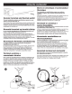
Wiring the Loudspeaker 1 25.0 mm II 0.25" 6.4mm --=:::::> I\ ~ ~ A 8 c Preparing the wire Preparation du cable Trim back the outer jacket (A) and some of the wire insulation (B) to expose enough bare wire (C) to attach to the terminals. Denuder Ia gaine externe (A) et une partie plus courte de l'isolant des fils (B) afin d'exposer Ia longueur de fil nu (C) necessaire au branchement.
Wiring the Loudspeaker 8Q 70V/100V *, - - - - - - - - - - I I L _____ _ _j *Optional wiring knockout *Debouchure facultative A second wire hole is available for running separate wires in and out of the loudspeaker. Use a flathead screwdriver to remove the knockout from the junction box cover. Un second orifice est disponible pour le passage de fils separes en entree et sortie de !'enceinte. Utiliser un tournevis tete plate pour faire sauter l'opercule du couvercle du boltier de jonction.
Wiring the Loudspeaker Borne en ceramique et commutateur thermique Pour repondre aux specifications propres aux systemes multiples en vigueur dans certaines zones d'Europe (voir page 17). Ceramic terminal and thermal switch To meet combination systems specifications required in some regions of Europe (see page 17).
Wiring the Loudspeaker ', .~, )// ..~..... / / 70V/100V sn / * r--- L---- *Optional wiring knockout *Debouchure facultative A second wire hole is available for running separate wires in and out of the loudspeaker. Use a flathead screwdriver to remove the knockout from the junction box cover. Un second orifice est disponible pour le passage de fils separes en entree et sortie de !'enceinte. Utiliser un tournevis atete plate pour faire sauter l'opercule du couvercle du boltier de jonction.
Installing the Loudspeaker 0 e Installing the loudspeaker in a ceiling 1. Remove cutting template from box. 2. Trace hole onto ceiling or tile- 10.5" (267 mm) diameter. 3. 4. 5. 6. Cut out hole. Insert loudspeaker. Locate anchor arm screws -A, B, C. Tighten anchor arm screws to secure loudspeaker. Do not overtighten screws. If using a power drill, set to a low torque setting [5 lb*in. - 8 lb*in. (5.8 kg*cm - 9.2 kg*cm)]. Installation af hejttaleren i et loft 1 . Fjern udskreringsskabelonen fra kassen.
Installing the Loudspeaker Installation de /'enceinte en plafond De luidspreker monteren in een plafond 1. Retirer le gabarit de decoupe de l'emballage. 1. Neem de montagesjabloon uit de doos. 2. Tracer au plafond ou sur le carrelage un trou de 270 mm de diametre. 3. Decou per ce trou. 2. Geef aan waar de opening (diameter van 267 mm) in het plafond of de tegel moet komen. 3. Zaag de opening uit. 4. lnserer I' enceinte. 4. Plaats de luidspreker in de opening. 5.
I Installing the Loudspeaker NOT INCLUDED: safety cable Using a safety cable • Some regional construction codes require the use of a secondary method of securing loudspeakers to support structures to provide additional safety. • Follow the safety cable manufacturer's instructions. • Choose a mounting position, method, and hardware consistent with local building codes and regulations.
Tap Settings * Factory default ** NC: No Connection (do not use) * Fabriksstandard ** NC: lngen forbindelse (undgfl brug) * Werkseitiger Standard ** NC: Keine Verbindung (nicht verwenden) * Ajuste de fabrica ** NC: Sin conexi6n (no utilizar) * Position par defaut ** NC : Non connecte (ne pas utiliser) * impostazioni predefinite ** NC: nessuna connessione (non utilizzare) * Fabrieksinstelling ** NC: Niet aangesloten (niet gebruiken) * Fabriksinstallningar ** NC: lngen anslutning (anvand inte) T
Grille Options Attaching the grille Removing the grille Using both hands, press the grille into place. Use a flathead screwdriver to gently remove the grille from the loudspeaker body. Be careful not to apply too much force, as that may cause the grille to bend. Montering af fronten Brug begge hc:ender til at trykke fronten pa plads. Fjernelse af fronten Gitter anbringen Drucken Sie das Gitter mit beiden Handen fest. Brug en flad skruetrc:ekker til forsigtigt at fjerne fronten fra selve h0jttaleren.
Safety and Regulatory Compliance The OS 40F has passed extensive testing and complies with the following specifications and uses: LISTED to ANSI/UL 1480-2005 • Fire Protective Signaling Use- UL Category UUMW, File NumberS 3241. Control Number 42S9. Not for use with De-supervised systems. • General-Purpose Use- UL Category UEAY, File Number S 5591 Control Number 3N89. • Suitable for use indoors in damp locations.
ROSE ® Better sound through research® 1111111111111111111111111111111111111111111 32561().0010 ©2013 Bose Corporation, The Mountain Framingham, MA 01701-9168 USA AM32561 0 Rev.03 pro.Bose.
The warranty information provided with this product does not apply in Australia and New Zealand. See our website at www.bose.eom.au /warranty or www.bose.eom.nz /warranty for details of the Australia and New Zealand warranty. -.---® Better sound through research® ©2012 Bose Corporation, The Mountain, Framingham, MA 01701-9168 USA AM355731 Rev.