LIFESTYLE® 18 DVD Home Entertainment System Installation Guide
Safety Information English WARNING: To reduce the risk of fire or electric shock, do not expose the system to rain or moisture. CAUTION AVIS RISK OF ELECTRICAL SHOCK DO NOT OPEN RISQUE DE CHOC ÉLECTRIQUE NE PAS OUVRIR CAUTION: TO REDUCE THE RISK OF ELECTRIC SHOCK, DO NOT REMOVE COVER (OR BACK). NO USER-SERVICABLE PARTS INSIDE. REFER SERVICING TO QUALIFIED PERSONNEL. AFIN DE PRÉVENIR UN CHOC ÉLECTRIQUE NE PAS ENLEVER LE COUVERCLE ARRIÈRE.
Contents Where to find … 5 5 6 7 7 8 8 9 10 10 12 13 13 13 13 14 14 14 15 16 17 17 18 19 19 Reference . . . . . . . . . . . . . . . . . . . . . . . . . . . . . . . . . . . . . . . . . . . . . . . . . . . . . . . . . . . . . . . . . . . . . . . . Using alternate system connections . . . . . . . . . . . . . . . . . . . . . . . . . . . . . . . . . . . . . . . . . . . . . To play VCR audio (not TV audio) through your system . . . . . . . . . . . . . . . . . . . . . . . . . . .
Introduction English Welcome Thank you for purchasing a LIFESTYLE® home entertainment system. If you have successfully installed your new LIFESTYLE® system using the Quick Set Up Guide, congratulations! You can now skip to “Finishing the installation” on page 19. If not, the information provided on the following pages will guide you through the installation. Region numbers Region numbers are assigned to DVD players and discs according to where they are sold.
System Installation Getting started English After unpacking your new system, save all packing materials. The original packing materials provide the safest way to transport your system if necessary. If any part of your system is missing or appears damaged, contact your authorized Bose® dealer immediately, or contact Bose directly. Refer to the Bose address list included with your system. The instructions in this section tell you how to connect your system as shown in Figure 1.
System Installation The following items are included with your system.
System Installation Placing your speakers CAUTION: Choose a stable and level surface for your speakers. Vibration can cause the speakers to move, particularly on smooth surfaces like marble, glass, or highly polished wood. If you are placing the center speaker on top of the television, attach the rubber feet provided to the bottom of the speaker. You may obtain additional rubber feet by contacting Bose® customer service. Refer to the Bose address list included with your system.
System Installation English Figure 4 Left front Speaker placement and reflection rays Center Right front Acoustimass® module Left surround Right surround Center speaker placement The sound from the center speaker should appear to come directly from the center of the picture. The center speaker cable allows up to 20 feet (6.1 m) distance from the Acoustimass module. 1. Place the center speaker directly above or below the center of the TV screen, or at the closest convenient location.
System Installation Acoustimass® module placement Follow these guidelines to select a location for the Acoustimass module: • Place the Acoustimass module along the same wall as the TV, or close to the same end of the room as the front speakers (see Figure 4). Note: To avoid interference with the TV picture, place the Acoustimass module at least 18 inches (45 cm) from the TV.
System Installation Placing your media center English Note: Now is a good time to find the serial number on the bottom of the media center, before you proceed. Copy that number onto your warranty card and in the space provided on page 2 of this guide. Select a location for the media center, keeping in mind the following guidelines: • Do not block the front of the media center. Make sure you allow enough room to lift up the front cover and open the CD tray of the CD/DVD player.
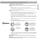
System Installation Figure 7 Terminal tab English Connecting speaker cables to the cube speakers Red (+) wire 1. Match the correct cable to the corresponding speaker location. Front speaker cables have blue connectors at one end, with L (left), R (right), or C (center) molded into the connectors. The red collars on the + wire are labeled LEFT, RIGHT, and CENTER. Surround speaker cables have orange connectors at one end, with L (left) or R (right) molded into the connectors.
System Installation Connecting the Acoustimass® module to the media center English Connect the Acoustimass module to the media center with the audio input cable (Figure 9). Note: Be sure that each connector is fully inserted into each jack. 1. Plug the small black multi-pin connector (flat side facing up) into the SPEAKER ZONES jack labeled “1” on the back of the media center. 2.
System Installation Connecting the antennas Note: Outdoor antennas may be used. To install an outdoor antenna, consult a qualified installer. Follow all safety instructions supplied with the antenna. Figure 10 Connections for the AM and FM antennas FM dipole antenna lead AM antenna lead TV SENSOR RECORD 33V DC POWER 1.
System Installation Connecting your TV to the system English The media center provides audio and video connections for your TV. See Figure 11. Making audio connections Using the supplied stereo audio cable, connect the left (L) and right (R) audio outputs on the rear panel of your TV to the L and R TV audio inputs on the rear panel of the media center (Figure 12). Making video connections These connections will vary according to the type of cable you use as described below.
System Installation Note: Component video jacks are often color-coded and it is essential that you match the color-coded connections with the cables. Figure 12 Media Center Component video adapter connections Component video adapter Your TV Pr (Red) Y (Green) Pb (Blue) S-VIDEO OUTPUT COMPOSITE VIDEO OUTPUT Connecting your VCR to the system (optional) The type of video connection used with your TV must match the type of connection used with your VCR, if you choose to connect it to the system.
System Installation Connecting your cable/satellite box to the system (optional) English The type of video connection used with your TV and VCR must match the type of connection used with your cable/satellite box, if you choose to connect it to the system. If you connected your TV to the COMPOSITE VIDEO OUTPUT, connect your cable/satellite box output to the COMPOSITE VIDEO INPUT. If you connected your TV to the S-VIDEO OUTPUT, connect your cable/satellite box to the S-VIDEO INPUT.
System Installation Installing the TV on/off detector (optional) Note: This device will not work with LCD and plasma TVs, so you may want to skip these steps. 1. Plug the connector on the end of the cord into the TV SENSOR jack on the back of the media center. 2. Position the TV on/off detector on the back of your TV as shown in Figure 15. Note: DO NOT use the mounting strip yet to affix the detector.
System Installation Connecting the system to power English Connect the two AC power (mains) cords in the following order: 1. Plug the small end of the Acoustimass® module power cord into the AC power jack on the connector panel of the Acoustimass module (Figure 16). Plug the other end of the power cord into an AC (mains) outlet. 2. Turn the Acoustimass module POWER switch to on ( l ).
System Installation Installing the remote control batteries Replace the batteries when the remote control stops operating or its range seems reduced. Alkaline batteries are recommended. Note: Do not change the settings of the factory-preset miniature switches. See your Operating Guide for information on how to prevent conflicts with other LIFESTYLE ® music systems.
System Installation English To get started 1. Turn your television on. 2. Lift up the media center front cover and press the Open/Close button. 3. Insert Setup Disc 1 into the tray (label side up) and press the Open/Close button again. 4. On the remote control, press the CD/DVD button. 5. As the disc begins to play, listen carefully and follow the instructions given to you. The instructions will tell you when to play Disc 2.
Reference Using alternate system connections English The following describes alternate ways to connect your VCR and TV to your LIFESTYLE® home entertainment system. To play VCR audio (not TV audio) through your system Connect the VCR audio outputs to the TV or VCR inputs of the media center as in Figure 1 on page 5, but do not connect the TV audio outputs. In this configuration, your VCR audio is played through your system, but the TV audio is played directly from the TV.
Reference English To play TV audio through your system with VCR audio fed to the TV Connect the VCR audio outputs to the audio inputs of the TV. Connect the TV audio outputs to the TV inputs on the media center. In this configuration, the LIFESTYLE® system TV source must always be selected.
Reference Setting up a second listening zone English Your LIFESTYLE® home entertainment system can direct sound from one or two sound sources (such as CD, AM/FM tuner, TAPE, or AUX) to two different listening zones at the same time. What is a zone? Each listening area, whether a room or a group of rooms (including outdoor areas), is called a zone. Your primary listening area is set up as zone 1.
Reference Connecting external equipment English Other equipment can be connected to your system using standard RCA audio cables. Be sure to match the red connector to the R (right) channel and the white (or black) connector to the L (left) channel. A Y adapter can be used to connect mono sources. The appropriate cables are available at most electronic stores.
Reference Connecting other playback equipment English Other playback components such as an audio CD changer can be connected to the AUX inputs on the rear panel of the media center. Figure 23 AUX input connections TV SENSOR RECORD 33V DC POWER 1.
Reference Connecting the optional IR emitter cable English The IR (infrared) emitter cable is designed for optional use with system components that are connected to the media center, but placed where they cannot receive IR signals from it. This can resolve the problem when a particular component does not respond to LIFESTYLE® remote control commands.
Reference Technical information English Media Center power pack power rating USA/Canada: 120V 0.55A 50/60 Hz 33VDC 1.1A International: 220-240V 0.30A 50/60 Hz 33VDC 1.1A Dual voltage: 115/230V 0.55A 50/60 Hz 33VDC 1.
©2003 Bose Corporation, The Mountain, Framingham, MA 01701-9168 USA 269712 AM Rev.