CONTENTS Safety Information.............................................................................................................................2 Warranty .............................................................................................................................................2 Product Description ..........................................................................................................................3 Accessories ..................................................
SAFETY INFORMATION 1. Parts that have special safety characteristics are identified by the symbol on schematics or by special notes on the parts list. Use only replacement parts that have critical characteristics recommended by the manufacturer. 2. Make leakage current or resistance measurements to determine that exposed parts are acceptably insulated from the supply circuit before returning the unit to the customer. Use the following checks to perform these measurements: A.
PRODUCT DESCRIPTION The 3•2•1 Series II Home Entertainment System is the replacement for the 3•2•1 and 3•2•1GS Series I Home Entertainment Systems. It uses the same system concept of a console with a dedicated bass module with TrueSpaceTM signal processed surround sound from 2 satellite arrays. The console will play video DVDs, DVD-R and DVD+R discs, audio CDs, Video CDs, CD-R and CD-RWs, and MP3 CDs. MP3 disc tracks must be burned in a single closed session.
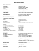
SPECIFICATIONS System Specifications: Power Rating: US/Canada: Europe/UK/Aus: Japan: Dual Voltage: 120VAC, 60 Hz, 300W 220-240VAC, 50/60 Hz, 300W 100VAC, 50/60 Hz, 300W 115/230VAC, 50/60 Hz, 300W Console Inputs: VIDEO, CAB/SAT, AUX Video Outputs: Composite Video, S-Video, Component Video External Antennas: FM, 75 Ohm F-Connector (PAL, Europe) AM Loop, 2.
SPECIFICATIONS System Specifications (continued): Noise when Muted: < 400 uVrms, A-weighted DC Offset: < 50 mVdc, all channels Channel Balance: +/- 1.
SPECIFICATIONS Console Specifications (continued): Optical S/PDIF Input Characteristics: Sampling Rates Accommodated: Number of bits recognized: Error Checking and Handling: Input Connector: 38 kHz, 44.1 kHz and 48 kHz 16, 20 and 24 Implements full error checking and handling, considering CRC, validity bit, loss of lock, parity error, and bi-phase error. TOSLINK Volume Control: 0 dB to full attenuation in 100 steps (100 - 0 indicated). 0 volume causes the amplifiers to mute.
SPECIFICATIONS Console Specifications (continued): Adjacent Chan Selectivity (200 kHz): 13 dB nominal / 10 dB limit @ 45 dBf Alternate Chan Selectivity (400 kHz): US/Can/Dual/Japan: Euro/UK/Aus: 70 dB nom/65 dB limit @ 45 dBf 75 dB nom/70 dB limit @ 45 dBf Image Rejection: US/Can/Dual/Japan: Euro/UK/Aus: RF Intermodulation: 45 dB nominal / 40 dB limit Meets FTZ (Fernmelde Technischer Zentralamt) requirement 65 dB nominal / 55 dB limit Sub-carrier Product Rejection (at speaker): 55 dB nominal / 45 dB
ELECTROSTATIC DISCHARGE SENSITIVE (ESDS) DEVICE HANDLING This unit contains ESDS devices. We recommend the following precautions when repairing, replacing or transporting ESDS devices: • Perform work at an electrically grounded work station. • Wear wrist straps that connect to the station or heel straps that connect to conductive floor mats. • Avoid touching the leads or contacts of ESDS devices or PC boards even if properly grounded. Handle boards by the edges only.
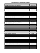
FREQUENTLY ORDERED ITEMS Main Assemblies CONSOLE ASSY, DVD, 120V, GRAPHITE, REGION 1 ASSEMBLY, BASS MODULE, 120V, GRAPHITE Part Number 270900-11119 273031-11119 Arrays ARRAY ASSY, 321 II, GRAPHITE ARRAY ASSY, 321GS II, GRAPHITE ARRAY ASSY, 321GS II, SILVER Part Number 255198-001 269990-001 269990-003 Remote Control REMOTE, IR, 3.2.
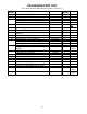
PACKAGING PART LIST 3•2•1 Series II Home Entertainment System (see Figure 1) Item Number 1 2 3 4 5 6 7 8 9 10 11 12 13 14 15 16 17 18 19 - Description Part Number COMMITMENT LETTER SHEET, QUICKSTART, GLOBAL ACCESSORY KIT, 321 II US, GRAPHITE ACCESSORY KIT, 321 II GS, US, GRAPHITE ACCESSORY KIT, 321 II GS, US, SILVER LINE CORD, 120V, POL, DET, GRAPHITE 251001 274561 273041-011 273041-111 273041-311 260082-001 Qty per System 1 1 1 1 1 1 BAG, POLY, 13.5 x 35 x 9.5 x 2.
1 2 3 4 5 6 7 9 10 8 ARRAYS (ITEM 10) INSIDE EPS FOAM 11 8 12 13 14 15 16 17 18 19 Figure 1.
PACKAGING PART LIST 3•2•1 Series II Home Entertainment System Accessory Kit (see Figure 2) Item Number 1 2 3 4 5 6 7 8 9 10 11 12 13 Description Part Number CARTON, DIE CUT, ACCESSORY KIT, 321 II CABLE, AUDIO, DUAL RCA ANTENNA, FM DIPOLE, 75 OHM, F CONN CABLE, VIDEO, 6', YL REMOTE, IR, 321 II ANTENNA, ASSY, AM, CD 20 BAG, POLY,3 X 3 MIL BATTERY, CARBON, AA SIZE CABLE, STANDARD ARRAY, 9 PIN, GRAPHITE CABLE, GEMSTONETM ARRAY, 9 PIN, GRAPHITE CABLE, GEMSTONE ARRAY, 9 PIN, SILVER BUMPER, RECESSED, FOOT, .
MAIN PART LIST 3•2•1 Series II Console Assembly (see Figure 3) Item Number 1 2 3 4 5 6 7 8 9 10 11 12 13 14 15 16 17 18 19 20 21 22 23 24 25 26 27 28 29 30 31 32 33 34 Description COVER, GATE (USED TO COVER RECESSS IN THE TOP COVER, ITEM 3 BELOW) PRESSURE SENSITIVE ADHESIVE, DIE-CUT (USED TO SECURE ITEM 1 TO ITEM 3) COVER, CONSOLE, DVD, GRAPHITE SHIELD, UPPER, COVER GASKET, EMI (FM ANTENNA CONNECTOR) PCB ASSY, TUNER, PROGRAMMED, US DRIVE, DVD-ROM, 1712, XQ1B10 CABLE, RIBBON, ATAPI, 40 POS, 260 MM CABLE, P
1 2 3 4 6 5 7 8 9 10 4x 11 12 14 13 16 15 17 18 26 27 30 32 34 19 25 20 28 31 33 21 29 3x 22 4x 24 Figure 3.
MAIN PART LIST Bass Module (see Figure 4) Item Number 1 2 3 4 5 6 7 8 9 10 11 12 13 14 15 16 17 Description FOAM TAPE, .32" W SCREW, TAPP, 8-11 x .5, PAN, ASY, SQ BRACKET, COVER, AMP SCREW, MACH, SEMS, WSHR, 10-32 x 0.5 TRANSFORMER, EI, 100V, 50/60HZ (120V SYSTEMS) TRANSFORMER, EI, 115/230V, 50/60HZ, R90 (DUAL VOLTAGE SYSTEMS) ENCLOSURE, REAR, GRAPHITE (120V) ENCLOSURE, REAR, GRAPHITE (DUAL VOLT) SCREW, 6-32 x 1/2 THREAD ROLLING CABLE, INPUT / OUTPUT, DIGITAL SCREW, TT, 8-32 x 0.
MAIN PART LIST Standard 3•2•1 Array Assembly (see Figure 5) Item Description Number 1 GRILLE, ARRAY, GRAPHITE 2 NAMEPLATE, BOSE® LOGO Note: Only the parts listed above are replaceable. Part Number 255196-001 255177-001 RED RED Qty per Array 1 1 Note BLACK REAR PANEL TERMINAL STRIP BLACK TWIDDLER DRIVER TM BLACK 1 RED ARRAY ENCLOSURE RED TWIDDLER DRIVER BLACK 2 Figure 5.
MAIN PART LIST 3•2•1 GS Array Assembly (see Figure 6) Item Number 1 2 3 4 5 Description Part Number TWIDDLER DRIVER ASSY, 50MM GRILLE, METAL, ARRAY, GRAPHITE GRILLE, METAL, ARRAY, SILVER NAMEPLATE, BOSE, ARRAY FOAM, GRILLE, ARRAY SCREW, HILO, 4-16 x .375, PAN, XREC 273244-001 273748-001 273748-003 269981-001 272036-001 181621-06 1 2 3 1 4 4x 5 8x Figure 6.
ELECTRICAL PART LIST Console Main PCB Assembly Resistors Reference Designator JP1 R4 R8 R10 R11 R13 R14 R15 R17 R19 R20 R21 R22 R30 R33 R35 R36 R37 R40 R42 R43 R44 R3200 R3202 R3203 R3204 R3206 R3207 R3215 R3216 R3217 R4000 R4001 R4003 R4005 R4006 R4008 R4009 R4010 R4013 R4014 R4016 R4024 R4025 R4038 R4090 Description Part Number JUMPER, CHIP, 0603 33.2K, 0603, 1/10W, 1% 1K, 0603, 1/10W, 1% 9.09K, 0603, 1/10W, 1% 39.2K, 0603, 1/10W, 1% 9.09K, 0603, 1/10W, 1% 18.
ELECTRICAL PART LIST Console Main PCB Assembly Resistors (continued) Reference Designator R4091 R4099 R4100 R4101 R4102 R4103 R4104 R4105 R4106 R4107 R4108 R4109 R4110 R4111 R4112 R4113 R4114 R4115 R4116 R4117 R4118 R4119 R4120 R4121 R4122 R4200 R4201 R4202 R4217 R4218 R5000 R5001 R5002 R5003 R5004 R6200 R6201 R6210 R6212 R6213 R6214 R6215 R6314 R6315 R6317 R6319 Description Part Number 1.00K, 0805, 1/10W, 1% 10K, 0603, 1/10W, 1% 1.00K, 0805, 1/10W, 1% 1.00K, 0805, 1/10W, 1% 1.00K, 0805, 1/10W, 1% 1.
ELECTRICAL PART LIST Console Main PCB Assembly Resistors (continued) Reference Designator R6500 R6501 R6502 R6503 R6504 R6505 R6506 R6510 R6511 R6512 R6513 R6514 R6521 R6522 R6523 R6524 R6700 R6701 R6704 R6705 R6706 R6707 R6718 R6719 R6809 R6810 R6811 R6812 R6813 R6815 R6816 R6818 R6819 R7000 R7001 R7002 R7003 R7004 R7005 R7007 R7008 R7009 R7010 R7013 R7014 R7015 Description Part Number 100 OHM, 0603, 1/10W, 5% 100 OHM, 0603, 1/10W, 5% 10K, 0603, 1/10W, 5% 100 OHM, 0603, 1/10W, 5% 2.
ELECTRICAL PART LIST Console Main PCB Assembly Resistors (continued) Reference Designator R7019 R7020 R7021 R7022 R7258 R7259 R7260 R7261 R7753 R7754 R7758 R7759 R7760 R8000 R8001 R8002 R8004 R8005 R8006 R8007 R8008 R8012 R8013 R8014 R8015 R8016 R8017 R8018 R8625 R8626 R8627 R9104 R9105 R9106 R9107 R9108 R9109 R9110 R9111 R9112 R9113 R9200 R9201 R9202 R9203 R9204 Description Part Number 1K, 0603, 1/10W, 5% 2.
ELECTRICAL PART LIST Console Main PCB Assembly Resistors (continued) Reference Designator R9205 R9206 R9207 R9208 R9209 R9210 R9211 R9212 R9213 R9214 R9752 R9756 R9757 Description Part Number 3.24K, 0603, 1/10W, 1% 14K, 0603, 1/10W, 1% 14K, 0603, 1/10W, 1% 3.24K, 0603, 1/10W, 1% 14K, 0603, 1/10W, 1% 14K, 0603, 1/10W, 1% 3.
ELECTRICAL PART LIST Console Main PCB Assembly Capacitors (continued) Reference Designator C51 C52 C53 C55 C56 C57 C58 C59 C74 C75 C76 C77 C78 C101 C107 C108 C3200 C4000 C4001 C4002 C4003 C4004 C4005 C4007 C4008 C4009 C4010 C4011 C4012 C4013 C4014 C4015 C4016 C4017 C4018 C4019 C4020 C4021 C4022 C4023 C4024 C4025 C4026 C4028 C4029 C4034 Description Part Number 0.047uF, 0805, X7R, 50V, 10% 680pF, 0603, X7R, 50V, 10% 1000uF, EL, 105C, 25V, 20% 0.10uF, 0603, 16V, 5% 0.047uF, 0805, X7R, 50V, 10% 0.
ELECTRICAL PART LIST Console Main PCB Assembly Capacitors (continued) Reference Designator C4035 C4036 C4037 C4039 C4040 C4041 C4042 C4043 C4044 C4045 C4046 C4047 C4048 C4049 C4050 C4051 C4199 C5000 C5002 C5004 C5006 C5008 C5010 C5012 C5013 C5014 C5015 C5016 C5017 C5018 C5019 C5020 C6200 C6201 C6202 C6203 C6204 C6206 C6207 C6208 C6209 C6210 C6211 C6212 C6213 C6215 Description Part Number 2200pF, 0805, X7R, 50V, 10% 0.047uF, 0805, X7R, 50V, 10% 0.
ELECTRICAL PART LIST Console Main PCB Assembly Capacitors (continued) Reference Designator C6216 C6219 C6221 C6225 C6226 C6300 C6504 C6505 C6700 C6701 C6702 C6703 C6705 C6706 C6708 C6710 C6807 C6808 C6809 C6810 C7000 C7001 C7002 C7003 C7004 C7005 C7006 C7007 C7008 C7009 C7010 C7011 C7012 C7013 C7014 C7015 C7016 C7017 C7018 C7019 C7020 C7021 C7022 C7023 C7024 C7026 Description Part Number 0.10uF, 0603, 16V, 5% 0.01uF, 0603, X7R, 50V, 10% 0.10uF, 0603, 16V, 5% 22uF, 1411, TANT, 6.
ELECTRICAL PART LIST Console Main PCB Assembly Capacitors (continued) Reference Designator C7250 C7251 C7252 C7254 C7255 C7256 C7257 C7258 C7259 C7260 C7261 C7262 C7263 C7264 C7265 C7266 C7267 C7268 C7269 C7270 C7271 C7272 C8001 C8002 C8003 C8004 C8005 C8006 C8013 C8014 C8016 C8017 C8018 C8019 C8020 C8021 C8436 C8437 C8621 C8622 C8625 C9102 C9200 C9201 C9202 Description Part Number 0.10uF, 0603, 16V, 5% 0.10uF, 0603, 16V, 5% 0.10uF, 0603, 16V, 5% 0.10uF, 0603, 16V, 5% 0.10uF, 0603, 16V, 5% 0.
ELECTRICAL PART LIST Console Main PCB Assembly Capacitors (continued) Reference Designator C9203 C9204 C9205 C9206 C9207 C9208 Description Part Number 220pF 0603, COG, 50V, 5% 220pF, 0603, COG, 50V, 5% 470pF, 0603, X7R, 50V, 10% 220pF, 0603, COG, 50V, 5% 220pF, 0603, COG, 50V, 5% 470pF, 0603, X7R, 50V, 10% Note 188454-221 188454-221 191470-471 188454-221 188454-221 191470-471 Inductors Reference Designator L1 L17 L5000 L5001 L5002 L5003 L5004 L5005 Description Part Number INDUCTOR, 300uH INDUCTOR
ELECTRICAL PART LIST Console Main PCB Assembly Diodes (continued) Reference Designator D6702 D6703 D6704 D6705 D6800 D6801 D7000 D7001 D8000 D8001 D8002 D8600 Description Part Number DUAL, SOT-23, BAV99 DUAL, SOT-23, BAV99 DUAL, SOT-23, BAV99 DUAL, SOT-23, BAV99 DUAL, SOT-23, BAV99 DUAL, SOT-23, BAV99 DUAL, SOT-23, BAV99 DUAL, SOT-23, BAV99 DUAL, SOT-23, BAV99 DUAL, SOT-23, BAV99 DUAL, SOT-23, BAV99 DUAL, SOT-23, BAV99 Note 147239 147239 147239 147239 147239 147239 147239 147239 147239 147239 147239 1
ELECTRICAL PART LIST Console Main PCB Assembly Integrated Circuits Reference Designator VR1 VR2 U2 U3 U17 U19 U4000 U6200 U6203 U6204 U6205 U6802 U7002 U7003 U8001 U8002 U8405 U8406 U9100 U9200 U9201 Description Part Number VREG, POS, D2 PAK, LD1086, 3.3V VREG, POS, D2 PAK, LD1086, 1.8V VOLT REG, 3.3V, 3.5A, SMPS COUNTER, BINARY, 8-BIT, TSSOP VOLT REG, 3.3V, 3.
ELECTRICAL PART LIST Console Tuner PCB Assembly Resistors Reference Designator R2000 R2001 R2002 R2003 R2004 R2005 R2006 R2007 R2008 R2009 R2010 R2011 R2012 R2013 R2014 R2015 R2016 R2017 R2018 R2019 R2020 R2021 R2022 R2023 R2024 R2025 R2026 R2027 R2028 R2030 R2031 R2032 R2033 R2073 R2074 R2075 R2076 R2077 R2078 R2079 R2080 R2081 R2082 R2083 R2084 R2085 Description Part Number 1K, 0603, 1/10W, 5% 120 OHM, 0603, 1/10W, 5% 150 OHM, 0603, 1/10W, 5% 100K, 0603, 1/10W, 5% 47K, 0603, 1/10W, 5% 2.
ELECTRICAL PART LIST Console Tuner PCB Assembly Resistors (continued) Reference Designator R2090 R2200 R2201 R2202 R2203 R7000 R7001 R7003 R7004 R7006 R7007 R7008 R7009 R7011 R7012 R7013 R7014 R7015 R7016 R7017 R7018 Description Part Number 100K, 0603, 1/10W, 5% 2.0K, 0603, 1/10W, 5% 2.0K, 0603, 1/10W, 5% 2.0K, 0603, 1/10W, 5% 2.0K, 0603, 1/10W, 5% 1.5K, 0603, 1/10W, 5% 1K, 0603, 1/10W, 5% 100 OHM, 0603, 1/10W, 5% 100 OHM, 0603, 1/10W, 5% 100 OHM, 0603, 1/10W, 5% 100 OHM, 0603, 1/10W, 5% 17.
ELECTRICAL PART LIST Console Tuner PCB Assembly Capacitors (continued) Reference Designator C2017 C2018 C2019 C2020 C2021 C2022 C2023 C2024 C2025 C2026 C2027 C2073 C2094 C2095 C2096 C2097 C2098 C2099 C2100 C2200 C7000 C7001 C7002 C7003 C7004 C7006 C7007 Description Part Number 22uF, EL, 85C, 16V, 20% 560pF, 0603, X7R, 50V, 10% 47uF, EL, 85C, 16V, 20% .01uF, 0603, X7R, 50V, 10% 10uF, EL, 85C, 16V, 20% 10uF, EL, 85C, 16V, 20% 10uF, EL, 85C, 16V, 20% .047uF, 0805, X7R, 50V, 10% 3.3uF, EL, 85C, 35V, 20% .
ELECTRICAL PART LIST Console Tuner PCB Assembly Transistors Reference Designator Q2000 Q2001 Q2002 Q2073 Q7000 Q7001 Description Part Number P, 50V, 2SA1341 BPLR, N, 25V, 30MA, SOT-23 JFET, N, 20V, 20mA, TO-92 BPLR, N, 40V, 200mA, SOT23 P, 50V, 2SA1341 BPLR, N, 50V, 100mA, SOT23 Note 146818 187601-001 148590-E 146819 146818 146817 Integrated Circuits Reference Designator U18 U19 U2000 U2074 U7000 U7001 Description Part Number VOLT REG, SMD, POS, SOT89, +10V VOLT REG, SMD, POS, SOT89, +5V AM/FM TU
ELECTRICAL PART LIST Bass Module DSP/Amplifier PCB Assembly Resistors Reference Designator R8 R9 R10 R12 R13 R14 R15 R16 R17 R18 R19 R20 R21 R22 R23 R24 R25 R26 R150 R151 R152 R162 R163 R164 R165 R250 R251 R252 R262 R263 R264 R265 R350 R351 R362 R363 R364 R365 R450 R451 R452 R453 R454 R455 R456 R457 Description Part Number 1.00K, 0805, 1/10W, 5% 3.30K, 0805, 1/10W, 5% 10.0K, 0805, 1/10W, 5% 1.00K, 0805, 1/10W, 5% 20.0K, 0805, 1/10W, 5% 1.69K, 0603, 1/10W, 1% 3.32K, 0603, 1/10W, 1% 49.
ELECTRICAL PART LIST Bass Module DSP/Amplifier PCB Assembly Resistors (continued) Reference Designator R1001 R1005 R4200 R4201 R4202 R4203 R4204 R4300 R4301 R4302 R4500 R4501 R4503 R4505 R4600 R4602 R4603 R4604 R4700 R4701 R6000 R6001 R6100 R6101 R6102 R6103 R6104 R6105 R6500 R6502 R7000 R7001 R7100 R7102 R7103 R7104 R7105 R7106 R7107 R7108 R7109 R7110 R7111 R7112 R7113 R7114 Description Part Number 510 OHM, ARRAY, SMT, 4 POS, 5% 510 OHM, ARRAY, SMT, 4 POS, 5% 4.
ELECTRICAL PART LIST Bass Module DSP/Amplifier PCB Assembly Resistors (continued) Reference Designator R7200 R7201 R7202 R7203 R7204 R7205 R7206 R7207 Description Part Number 100K, 0603, 1/10W, 5% 10K, 0603, 1/10W, 5% 4.7K, 0603, 1/10W, 5% 4.7K, 0603, 1/10W, 5% 47 OHM, 0603, 1/10W, 5% 1M, 0603, 1/10W, 5% 10K, 0603, 1/10W, 5% 4.
ELECTRICAL PART LIST Bass Module DSP/Amplifier PCB Assembly Capacitors (continued) Reference Designator C62 C150 C151 C152 C153 C154 C155 C156 C157 C158 C159 C160 C161 C250 C251 C252 C253 C254 C255 C256 C257 C258 C259 C260 C261 C350 C351 C352 C353 C354 C355 C356 C357 C358 C359 C360 C361 C362 C363 C364 C365 C1000 C1001 C1002 C1003 C4000 Description Part Number 2.2uF, FILM, 100V, 10% 100uF, EL, 85C, 25V, 20% .047uF, 0805, X7R, 50V, 10% .01uF, 0603, X7R, 50V, 10% .01uF, 0603, X7R, 50V, 10% .
ELECTRICAL PART LIST Bass Module DSP/Amplifier PCB Assembly Capacitors (continued) Reference Designator C4001 C4002 C4003 C4104 C4105 C4200 C4300 C4301 C4302 C4303 C4304 C4306 C4307 C4308 C4308 C4309 C4309 C4310 C4310 C4400 C4401 C4500 C4501 C4600 C4601 C4602 C6000 C6100 C6101 C6102 C6105 C6500 C7000 C7001 C7002 C7003 C7004 C7005 C7006 C7007 C7008 C7009 C7011 C7012 C7108 C7109 Description Part Number .047uF, 0603, X7R, 50V, 10% .047uF, 0603, X7R, 50V, 10% .
ELECTRICAL PART LIST Bass Module DSP/Amplifier PCB Assembly Capacitors (continued) Reference Designator C7110 C7111 C7114 C7115 C7116 C7200 C7300 C7301 C7302 C7303 Description Part Number 4700pF, 0603, X7R, 50V, 10% 47pF, 0603, COG, 50V, 5% 4700pF, 0603, X7R, 50V, 10% .01uF, 0603, X7R, 50V, 10% .01uF, 0603, X7R, 50V, 10% .047uF, 0603, X7R, 50V, 10% .047uF, 0603, X7R, 50V, 10% .047uF, 0603, X7R, 50V, 10% .047uF, 0603, X7R, 50V, 10% .
ELECTRICAL PART LIST Bass Module DSP/Amplifier PCB Assembly Transistors Reference Designator Q2 Q3 Q4 Q5 Q450 Q451 Q452 Q6100 Q6101 Q7200 Description Part Number BPLR, N, 40V, 200mA, SOT23 BPLR, N, 40V, 200mA, SOT23 MOSFET, P, 60V, 17A, TO-220 BPLR, N, 40V, 200mA, SOT23 BPLR, N, 50V, 100mA, SOT23 BPLR, N, 50V, 100mA, SOT23 BPLR, PNP, 500MA, SOT23 BPLR, N, 40V, 200mA, SOT23 BPLR, N, 50V, 100mA, SOT23 BPLR, N, 50V, 100mA, SOT23 Note 146819 146819 271765-001 146819 146817 146817 189290-001 146819 146817
ELECTRICAL PART LIST Bass Module Input/Output PCB Assembly Capacitors Reference Designator C1 C3 C4 C5 C6 C8 C9 C10 Description Part Number 2.2uF, EL, 85C, 50V, 20% 2.2uF, EL, 85C, 50V, 20% 2.2uF, EL, 85C, 50V, 20% 2.2uF, EL, 85C, 50V, 20% 4700uF, EL, 105C, 50V, SNAP .01uF, 0805, X7R, 50V, 10% .01uF, 0805, X7R, 50V, 10% 2.
DISASSEMBLY PROCEDURES Console Procedures 1. Outer Bezel Removal 1.1 Remove the DVD drawer bezel. To do this, you will need to either apply power to the console and press the EJECT button, or use the manual DVD drawer eject function. This is done by placing a small screwdriver into the front of the slot located in the bottom of the bezel sub-assembly and rapidly moving the screwdriver toward the rear of the console. This will press in the built-in eject pin and cause the DVD drawer to open. 1.
DISASSEMBLY PROCEDURES 2.3 Grasp the console between the top and bottom of the unit, ensuring that you have a good grip on the unit, and carefully flip the console over onto its feet. Lift the top cover straight off. 3. Inner Bezel Sub-assembly Removal (includes Button PCB, IR Receiver PCB and Display PCB) 3.1 Perform procedure 2. 3.2 Unplug the inner bezel sub-assembly ribbon cables from J6500 and J6700 on the main PCB. 3.
DISASSEMBLY PROCEDURES 4. Tuner PCB Removal 4.1 Perform procedure 2. 4.2 Lift up on the forward edge of the and slide it toward the front of the console until the PCB jacks clear the rear panel. Lift the PCB straight up. 4.3 Unplug the tuner PCB ribbon cable from J6000 on the main PCB. Re-assembly Notes: - Make sure that the RF gasket is in place on the FM antenna connector when re-installing the PCB assembly.
DISASSEMBLY PROCEDURES Re-assembly Note: Be sure to install the DVD drawer eject pin into the manual eject hole in the front of the drive before reinstalling the bezel assembly. 6. Main PCB Assembly Removal 6.1 Perform procedure 5. 6.2 Lift up the front edge of the main PCB assembly. Slide the PCB forward until the jacks clear the back panel. Lift out the PCB assembly. Re-assembly Notes: 1. Make sure that the RF gasket is in place on top of the Bose Link connector when reinstalling the PCB assembly. 2.
DISASSEMBLY PROCEDURES 2.3 Using a phillips-head screwdriver, remove the four screws that secure the heatsink bracket to the heatsink. Lift off the heatsink bracket. 2.4 Carefully lift the main PCB away from the heatsink. Unplug the power transformer secondary harness from the main PCB at J5. Rotate the main PCB clear of the cabinet until it is at about 90 degrees from the heatsink. At this point, you should be able to lift the PCB clear of the rear enclosure mounting brackets. 3.
DISASSEMBLY PROCEDURES Standard Satellite Array Procedures Notes: • The standard satellite arrays are nonrepairable. These are the arrays that have the cloth grilles, and are physically larger than the GemstoneTM array. • The only parts that can be replaced on the standard arrays are the grille and the nameplate. Refer to the photos at right for the following procedures. 1. Grille Removal 1.1 Wrap some masking tape around the shaft of a flat-tip screwdriver approximately 1/2" back from the end.
TEST PROCEDURES 3•2•1 Series II Required Test Equipment and Cables Note: In order to perform these tests you will need the bass module and the console, along with an IR remote control for the user interface tests. The bass module provides DC power to the console for all but the AM and FM tests, and also provides signal processing to the arrays. 1. Audio signal generator 2. Analog to S/PDIF converter 3. S/PDIF to optical converter 4. Abex test DVD (TDV-540A) 5. Video monitor 6. Composite video cable 7.
TEST PROCEDURES 1. Initial Product Test Note: Before taking the unit apart or performing any repair process, an attempt to verify the customer complaint must be made. 1.1 Read any customer note included with the unit. 2. Verify Customer Complaint 2.1 Attempt to verify the customer complaint before opening the unit or performing any repairs. Customer complaint not verified, discuss with customer. 3. Check the software revision of the unit Refer to the Bose® Service extranet web site at http://serviceops.
TEST PROCEDURES 2. AM Stop Level Test AM Performance Tests 2.1 Set the RF generator to 1080 kHz, AM modulation, 1 kHz, 30% modulation, 61 dBuV/M. AM Tuner General Test Setup Set up an AM loop antenna as shown. 2.2 Place the unit into seek mode, and verify that it stops at 1080 kHz. 2.3 Switch the RF generator for a 51 dBuV/ M field intensity and verify that the unit does not stop at 1080 kHz.
TEST PROCEDURES 5.
TEST PROCEDURES 7. User Interface Tests Console Test Cable Fabrication 7.1 Press each button on the console control panel and ensure its operation. Items Needed: 3•2•1 Series II cable, P/N: 269997-001 1 - Red center female RCA jack 1 - White center female RCA jack 7.1.1 With the media center off, connect an external video source to the UUT’s external video inputs. Verify that the video appears on the video monitor. Do this for both the composite and S-Video outputs on the media center.
J100 J201 J202 J8000 T8600 J9640 U6203 U8001 U4000 U9100 J9341 J3200 U6200 U8002 U8405 U8406 U9201 U7003 U9200 VR2 VR1 J3202 J6700 U9641 U6802 J6200 U17 J6500 U2 U3 J3 J2 Note: The IR Receiver PCB and the Button PCB are part of the Main PCB above Figure 7.
J100 J201 J202 J8000 T8600 J9640 U6203 U8001 U4000 U9100 J9341 J3200 U6200 U8002 U8405 U8406 U9201 U7003 U9200 VR2 VR1 J3202 J6700 U9641 U6802 J6200 U17 J6500 U2 U3 J3 J2 Figure 8.
J100 J201 J202 J8000 T8600 J9640 U6203 U8001 U4000 U9100 J9341 J3200 U6200 U8002 U8405 U8406 U9201 U7003 U9200 VR2 VR1 J3202 J6700 U9641 U6802 J6200 U17 J6500 U2 U3 J3 J2 Figure 9.
J100 J201 J202 J8000 T8600 J9640 U6203 U8001 U4000 U9100 J9341 J3200 U6200 U8002 U8405 U8406 U9201 U7003 U9200 VR2 VR1 J3202 J6700 U9641 U6802 J6200 U17 J6500 U2 U3 J3 J2 Figure 10.
U7001 U7000 U2074 T2000 U2000 T2002 T2001 J1 CF2001 CF2000 J2000 TNR2000 J2001 Figure 11.
U7001 U7000 U2074 T2000 U2000 T2002 T2001 J1 CF2001 CF2000 J2000 TNR2000 J2001 Figure 12.
J5 Q4 F1 J350 J150 U350 U150 U250 DS6500 U7300 U7000 U4000 U6100 U6000 U7200 J7100 U100 U101 U4400 Figure 13.
J5 Q4 F1 J350 J150 U350 U150 U250 DS6500 U7300 U7000 U4000 U6100 U6000 U7200 J7100 U100 U101 U4400 Figure 14.
J6 J7 J4 J3 C6 S1 J5 J2 J1 F1 J6 J7 J4 J3 C6 S1 J5 J2 J1 F1 Figure 15. Bass Module Input/Output PCB Topside Etch Layout Diagram Figure 16.
APPENDIX Obtaining System Information from the Media Center Display You can obtain system information directly from the media center display by pressing a few buttons. Follow the steps below. - Connect the media center and bass module as instructed in the owner’s guide. - Connect the system to AC mains. - With the media center turned off, press and hold the ENTER button on the media center.
DVD Lock options The DVD Lock options allow you to restrict viewing of DVD videos with certain ratings. To activate this feature, you need to set a level of restriction and establish a password in the DVD Lock section of the System menu.
DVD Lock options (continued): DVD Lock Bypass If a customer forgets his DVD Lock password, or if you have a system in for repair that is locked and will not let you play a DVD without a password, you can bypass the DVD Lock feature by following the steps below. 1. Select a non-DVD source and press the SYSTEM button on the remote. 2. Navigate to the “DVD Lock” icon on the far right of the TV screen and press ENTER. 3. The system will then request the user to enter a password.
GLOSSARY OF TERMS Aspect Ratio - The shape of the rectangular picture in a TV set. It is the width of the picture relative to the height. Our standard TV picture, is 4 units wide by 3 units high, or 4:3 in aspect ratio. There are currently two standard TV aspect ratios in the U.S., 4:3 and 16:9. Chapter - In DVD-Video, a division of a title. Technically called part of a title (PTT). Component Video - A video signal split into three parts, luminance and two color signals (marked as YPbPr).
SERVICE MANUAL REVISION HISTORY Date 8/04 Revision Description of Change Level 00 Document released at revision 00.
3 2 1 and 3 2 1GS Series II Home Entertainment System • • • • (US/Canada Standard Versions, 120V and Dual Voltage) 3•2•1 Series II System 3•2•1GS Series II System ©2004 Bose Corporation Service Manual Reference Number 273029-SM Rev.
SPECIFICATIONS AND FEATURES SUBJECT TO CHANGE WITHOUT NOTICE Bose Corporation The Mountain Framingham Massachusetts USA 01701 P/N: 273029-SM Rev. 00 9/2004 (H) http://serviceops.bose.