
User Manual


Table Of Contents
- About your Bose® A20® Aviation Headset
- Components
- Preparing the Headset for Use11
- The battery compartment
- Connecting the headset to the aircraft
- Wearing and adjusting the headset
- Using the control module
- Primary and secondary audio sources
- AUX audio sources (wired)
- Bluetooth® audio sources (wireless)
- Using the headset with a Bluetooth® device
- Pairing the first device
- Pairing another device
- Switching between connected devices
- Bluetooth multi-function button
- Making and answering calls
- Reconnecting to a previously connected device
- Recovering a lost connection
- Disconnecting a Bluetooth device
- Clearing the headset pairing list
- Controlling Bluetooth volume
- Using the headset with a Bluetooth® device
- Secondary audio modes
- Cleaning the headset
- Instructions for continued airworthiness
- Managing multiple secondary sources
- Ordering parts and accessories
- Contact information
- Limited warranty
- Locating the headset serial number
- Mounting the aircraft panel connector
- Replacing parts
- Microphone windscreen
Technical Information
38 - English
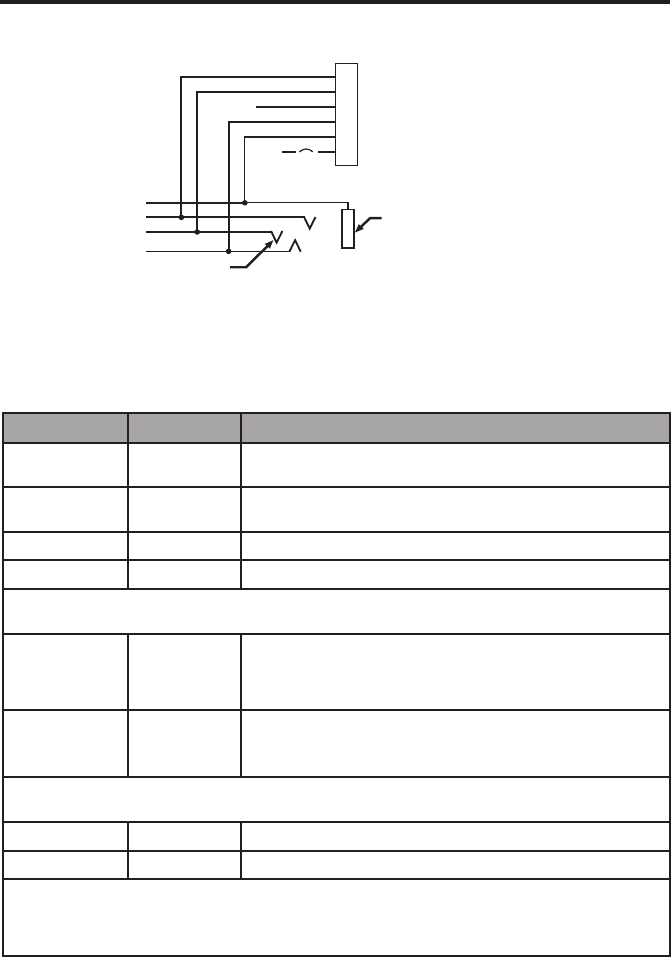
Helicopter (U174) connection diagram
Barrel
(audio gnd)
Existing single 4-
prong jack
Existing wiring to
helicopter intercom/
audio panel
Tip
(MIC HI)
10-32
V DC
6 MIC LO
5 MIC HI
4 COMM R
3 COMM L
2 GND
1 V+IN
1/2A
WHT/BLU
WHT
BLU
WHT
BLK
RED
Note: Barrel ground (gnd) refers to aircraft grounds.
Details on making the connections
The pinouts for the optional installed connector are detailed in the table below:
Pin number Color Purpose
1 Red V+IN: Headset power (10-32 VDC). Use a 1/4 amp fuse or
a 1/2 amp circuit breaker.
2 Black GND: System ground. Connect to the existing audio
ground.
3 White COMM L: Phone communication: Left.
4 Blue COMM R: Phone communication: Right.
Note: Monaural use cases should not tie left and right audio sources together due to auto
sensing systems found in many intercom systems.
5 White MIC HI: Microphone/Hi-audio. Connect to the portion of
the existing microphone jack that corresponds to the ring
position of a headset microphone plug. Do not connect to
the tip (PTT) segment.
6 White/Blue MIC LO: Microphone/Lo-ground. Connect to the portion
of the microphone jack that corresponds to the barrel
position of a headset microphone plug.
Note: If the microphone works on radio transmit but not through the intercom, check pin 6.
It may be incorrectly wired to the PTT segment of the microphone jack.
Comm Shield Black Shield from Comm L and Comm R wire pair.
Mic Shield Black Shield from Mic Hi and Mic Lo wire pair.
Note: The wires connecting pins 3 and 4 and pins 5 and 6 are shielded, twisted pairs with
a black wire shield termination exiting each pair. If the existing wiring is not shielded,
connect the shields to the existing audio wiring shields, or connect the shield from
Comm L and Comm R wire pair to audio ground.